SX User’s Manual Rev. 3.1
132
© 2000 Scenix Semiconductor, Inc. All rights reserved.
www.scenix.com
Chapter 4 Clocking, Power Down, and Reset
SX48/52BD:
•
LP1– low-power crystal (32 KHz)
•
LP2 – low-power crystal /resonator(32 KHz to 1 MHz)
•
XT1 – normal crystal/resonator (32 KHz to 8 MHz)
•
XT2 – normal crystal/resonator (1 MHz to 24 MHz)
•
HS1 – high-speed crystal/resonator (1 MHZ to 32 MHz)
•
HS2 – high-speed crystal/resonator (1 MHZ to 50 MHz
•
HS3 – high-speed crystal/resonator (1 MHZ to 100 MHz)
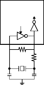
With the SX device configured in one of these modes, the crystal or ceramic resonator is connected to
the OSC1 and OSC2 pins as shown in Figure 4-2. The recommended external component values are
specified in the device datasheet.
If you use a crystal, a parallel resonant type crystal is recommended. Using a series resonant type
crystal may result in a frequency that is outside of the crystal manufacturer’s recommended range.
4.2.5
External Clock Signal
You can use an externally generated clock signal to drive the SX device. This mode is suitable for
systems in which there is already a clock signal available (used to drive other chips in the system) that
can also be used to drive the SX device. The clock signal must meet the clock specifications of the SX
device, including the duty cycle, rise time, fall time, and voltage levels.
Figure 4-2 Crystal or Ceramic Resonator Connections
SX Device
R F
XTAL
OSC2
OSC1
C1
C2
Internal
Circuitry
SLEEP
R S
