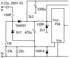
 This circuit
(from Jinx) counts mains cycles and supplies a small motor with 9V for about
1/2 second (dumped from the 3300u), adjustable timing / transistor drive
for this from a 4001 one-shot.
 This circuit
(from Jinx) counts mains cycles and supplies a small motor with 9V for about
1/2 second (dumped from the 3300u), adjustable timing / transistor drive
for this from a 4001 one-shot.
Wagner Lipnharski says:
Due the need for lowest possible current on this system and the half wave rectifier, your 9V zener could transfer a high ripple to the final 5V zener. I wonder if the ripple could not reach the limits of 5V already.To avoid this possible problem, I would increase the system filtering, but to do that you need to increase the power drain from the source, what would need a bigger input cap and lower impedances in general, or, increase the 9V zener to a little higher voltage one, as 12V for example.
The use of two zeners is a required safety procedure, since if the first zener blows up (open), your final circuit still protected by the second zener. I used a double configuration like that for a power meter with 0-1mA output, the Vdc is 12V and the primary zener is 33V.
You would want to use a HSF (low ESR) capacitor at the 5V PIC input, with a couple of 0.1µF.
The input cap (0.22µF) have different charge current for each senoid polarity. This is caused by your 9V zener that offers a 9V drop in one side of the senoid, while only 0.6V at the other senoid side. Remember that even with a nice current consume at the load, it is not the same as the full direct current flow through the zener.
I used a 1N4007 diode in series with the zener, with a resistor in parallel to this diode. This resistor value is to balance both senoid polarity current over the cap. Without much calculation, I guess the primary cap current is around 9mA, so a 820 Ohms resistor should generate a Vdrop enough to balance when the senoid is negative at the hot wire. You need to test it in the bench.
If you don't balance it, the cap will charge more than discharge, reducing the efficiency.
       |
       |
     ,---'
       A    12Vdc Zener
       |
       o---.
       |   |
1N     |   R  820 Ohms
4007  _V_  R
       |   |
       o---'
       |
       |
Dwayne Reid of Trinity Electronics Systems Ltd, Edmonton, AB, CANADA says:
I use something very similar, except adapted for 120 Vac 60 Hz. My inrush limiting resistor is either 150R 0.5W (with 1 uF input cap) or 2 - 150R 0.5W resistors in parallel with a 2u2 input cap. I also put a LED and series 150R resistor in parallel with the inrush limiting resistor as a power indicator. The importtant thing here is that the inrush resistor is much larger than you would normally expect, with the resistor being carbon composition instead of film.Getting back to the original circuit Jinx posted, I would change the 1n914 diode (at the line sample input on the PIC) to a 4v7 xener. It doesn't cost much more than the 1n914 and ensures that the PIC input doesn't see high voltage. This is especially important if the sample gies to input GP3 on an 8 pin pic.
The only other thing I use on some furnace controllers is a reset derived from the 5V supply. I use a cheapie pnp transistor (2n4403) wired with E to 5V rail, B to 4v3 zener cathode, C to reset with a pulldown resistor to gnd and a 100n cap from reset to vcc (across C-E of the transistor). Value of the pulldown depends whether I'm using an 8 pin pic or larger - the 8 pin PICs have a built in pullup which requires a lower value of pulldown resistor than normal. The anode of the 4v3 zener goes directly to gnd - the transistor / zener combo replaces the 5v zener in the original circuit.
This has the advantage of holding the PIC in reset until the zener is conducting - the 100n cap across the transistor stops small transients from resetting the pic. Shipped many thousands of those with NO failures.
See also: