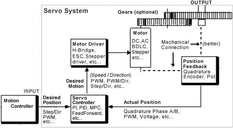
There are two classes of "Servo": "Hobby" or "RC" servos and industrial servos. Both are actually systems, including a motor of some type, with a built in position sensor and control system to move the shaft to the position request from some sort of data input.
RC Servos change position based on the duration of the positive part of the pulse received. The pulse can generally range from 1 to 2 milli-seconds with center at 1.5ms. If the pulse is 1.5ms, the servo will be centered. At 2.0ms, the servo will rotate 90' clockwise. At 1.0ms, it will be at -90' or 90' CCW. The frequency of the pulses is less critical, and most servos will function from 40 to 200Hz. The position feedback is generally (rare exceptions) a potentiometer attached to the shaft. Accuracy is typically no better than a degree or two. The control system is generally an analog electronic circuit which compares the input pulse duty cycle with the duty cycle of another pulse developed from the internal pot and then moves the motor based on the difference. E.g. it is Proportional only.
Industrial servos can be commanded to move with a wide range of input data including step/direction, PWM, serial ASCII data, and so on. They typically use optical or magnetic Quadrature Encoders to measure position, a control system which includes PI or PID control (like the BOB PID) and a driver to move the motor.
(click on the words in the picture below for more information)

Driver: The motor driver needs to match the motor: e.g.
Servo Controller: The "brains" of the operation. It figures out what motion to command based on the current desired position, actual position, and what it knows about the mechanics of the motor and mechanical setup. It needs to speak the language used by each of the parts it talks to... If the motor driver expects step and direction signals, and the control tries to feed it a PWM signal with center at 50% duty cycle, it's just not going to work. In the same way, it needs to understand the format of data the position encoder is putting out and the format of the commands from the motion controller. Quadrature encoders are the most common, but a voltage from a potentiometer is often used with smaller RC servo systems. The motion controller will generally put out step and direction signals. Our offering is the BOB PID Servo Controller
Position Feedback Encoder: Best connected to the actual output shaft, instead of the motor shaft, because then the system can compensate for slop in the gearing.
Gearing is most useful when used with a high speed DC or AC motor, because they typically don't have good low speed torque. A gear train allows us to trade their higher speed for strength at low speeds. Stepper motors often don't need gearing... or servo drive, for that matter...
When there is backlash between the output shaft and the motor shaft (caused
by the gearing) 2 encoders can be used. This is also applicable to systems
with a rotary encoder on the motor and a linear encoder on an axis. In this
case, the PID loop may struggle with the backlash using only the motor shaft
encoder. The two encoders may be combined by using the motor encoder for
the P and D terms and the output or axis encoder for the I
term^.
Another possibility is to use two PID loops, one inside and one outside.
Turn any motor into a servo with our Controller and Encoder:
NEW: MassMind.org BOB PID
Servo Controller
HOT:
MassMind Magnetic High Speed
Non-Contact Encoder
NEW:
MassMind.org H-Bridge DC Motor Driver
Servo control with a sound waveforms or from a web Browser
Servo control with the PIC Embedded controller
More:
See also:
Questions:
There are several non TMR2 PWM versions to be found in the PWM link above
Can anyone point me to information on how to take servo pulses from an R/C receiver (RX Unit) and convert those pulses to an integer form? I would like to make sort of a two channel mixing unit for my airplane. I'd take two servo pulses, convert them into integers, do some calculations on them, then convert them back into PWM for the servos. Thanks in advance!
See: Piclist post 2000/11/10/132825a "Fourier calc for tone detection" by Scott Dattalo