 Most people will use stepper motors make a complete
motion system.
Most people will use stepper motors make a complete
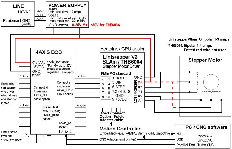
motion system. Click block diagram for larger version.
Most people will use stepper motors make a complete
motion system.
Click block diagram for larger version.
A stepper motor is a kind of electric motor with an internal rotor containing permanent magnets and a set of electro-magnet coils around the rotor which are switched electronically. Stepper motors "cog" to a limited number of positions, but with a microstepping controller, which partially activate adjacent coils so that the rotor rests between positions, stepper motors can rotate more smoothly.
Advantages: Stepper motors will try to lock to the position of the coil that is being driven by the controller so the position of the motor can be known without any actual position sensing. Although it is possible for the motor to be turned out of phase with the coil excitation, which is know as skipping or missing steps, in most cases the reduced cost of the system is justified. Also, stepper motors are "brushless" unlike most other motors and so generate less EMI or Noise.
Disadvantages include lower power efficiency, higher cost per unit, and the need for a more complex drive circuit aka driver. Also a much lower top speed. For example, a standard Lin Engineering brand 5718X-15P^ motor at 24 volts, 4.2 amps = 100 watts drive, will actually produce abount 45 watts of output power; 40 oz-in at 1500 RPM. And it will cost around $60 if you find a good deal. Just for comparison, an AmpFlow M27-150 DC motor^ at 24 volts, 5.3 amps = 128 watts will produce 100 watts of power. So 70% efficiency (79% at ~70W). And cost about $35. And a 200 watt DC motor H bridge will cost about $10. But then you need a position encoder, microcontroller, and a PID loop, which you must tune. And the brushes in the motor will burn out in a few thousand hours.
Control Signals: The stepper motor controller typically accepts two inputs, Step and Direction, from an external source, which is the Motion Controller. If the motion controller is a PC, then those signals can be transferred to the drivers via a Parallel Port connected BOB: "Break Out Board" (or cable) in real time or they can be generated via a Serial, USB, or Ethernet connected Embedded Motion Controller. One common standard for a cable/connector to carry these singals is the PMinMO standard.
The Direction signal set the direction of rotation and each pulse on the Step signal causes the driver to move the motor one step in that direction. The controller translates these signals into different patterns of current flow in the coils, which result in the moment of the motor. The Step signal may be called: Clock, CLK+, Pluse, etc.. and Direction may be called DIR, CCW+, CW/CCW, but they are still just carrying Step and Direction information.
Size: Type 23, NEMA 23 or any other like that refers to the mounting arrangement only (mounting hole pattern and size, diameter of shaft) Also: Table of NEMA sizes showing shaft, mounting hole positions, distance, etc...
Application: Stepper motors excel at driving loads needing up to about 100 Watts of power to move at less than a few hundred RPM with accuracy of 1/200th of a revolution. Lighter loads can be driven faster or with more accuracy. Stepper motors are commonly used to convert milling machines to CNC control.
Also:
See also:
http://www.bright.net/~agarb/STMD/STMD.html For those that are interested, I've been working on an open-source bipolar, microstepping chopper stepper drive. Schmatics are available and it is my intention to also make the source code availabe once I get it cleaned up.
See:
Comments:
Hi, I received your awesome motor driver kit, and will put it together and give an update once I have time (trying to build a fully automated injection molding machine at the moment!). I hope to use the drivers for a cnc machine for starting a local makerspace.
Thanks!
Jesse Urban
Questions: