 http://freeandeasy.sourceforge.net
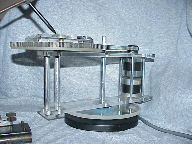
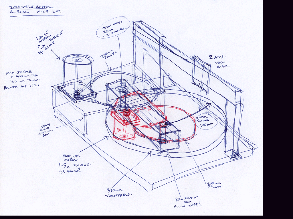
Crazy idea for a low cost, highly accurate CAM system which can be made without precision tools.
 http://freeandeasy.sourceforge.net


 Uses
a long bolt, with a nut holding the head of the bolt to the base plate then
a nut followed by a washer (small so it just covers the inner race) and then
the bearing, then another small washer and a nut. Repeat that for the second
bearing at the top... then between the two, there are large washers with
a very large hole that clear the small washer and nut and those washers are
drilled and screwed down to the top and bottom of the aluminum box tube.
These will probably have to be 4 of the large washers, above and below each
of the bearings. Perhaps the main wheel will go between two of these and
be a press fit around the outside of the bearing.

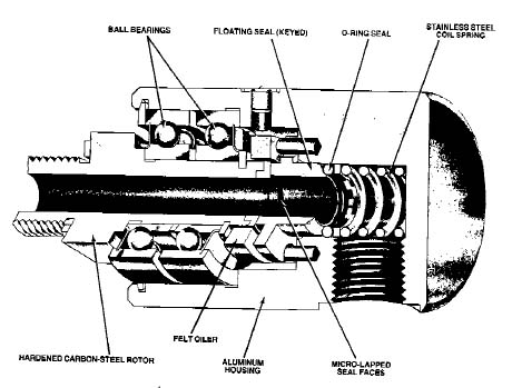
This shaft could be the same as the one above or it could use a rotary air joint in order to supply a vacuum vice in the second disk.
http://www.milllog.com/deublin.htm
http://www.tonymachinery.com/jointweb/productshowcase.htm
http://www.carymfg.com/pages/rotary.htm
http://www.carymfg.com/pages/rotary/main.htm
http://www.rotarysystems.com/index.htm
We have :
| Series | 23LQ-C |
| # of Models in Series | 3 |
| Machine Type | H |
| Size (mm) | N23 |
| Step Size (deg) | 5.0 |
| Best Accuracy (arcmin) | 15.0 |
| Cont. Holding Torque (N-cm) | 22.6 |
| Rated Current / Phase (A) | 1.0...2.0 |
| Nominal Voltage (VDC) | 3.4...6.8 |
| Series | 17PM-K |
| # of Models in Series | 10 |
| Machine Type | H |
| Size (mm) | N17 |
| Step Size (deg) | 1.8 |
| Best Accuracy (arcmin) | 5.4 |
| Cont. Holding Torque (N-cm) | 14.8 |
| Rated Current / Phase (A) | 0.4...1.2 |
| Nominal Voltage (VDC) | 3.0...10.0 |
We need:
See also:
Questions:
Who is the author of this article? I need some info on "AstroSyn PN: EM-217 Type: 17PM-K041-P2F NO: T4Y24". Can he/she contact me? Thank you in advance
James Newton replies: http://www.ni.com/devzone/advisors/motion/mineaba.htm Your unit (or at least its series) is listed there along with the specs.