Figure 6.7: Current-to-voltage converter.
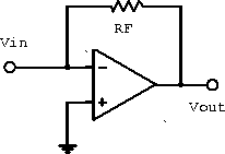
Consider the current-to-voltage converter shown in figure 6.7. Applying our ideal amplifier rules gives

Figure 6.7: Current-to-voltage converter.
![]()
Therefore ![]() and the circuit acts as a
current-to-voltage converter.
and the circuit acts as a
current-to-voltage converter.
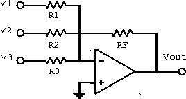
Figure 6.8 shows several current sources driving the negative input of an inverting amplifier. Summing the current into the node gives

Figure 6.8: Current summing amplifier.
![]()
Therefore
![]()
If ![]() , we have
, we have
![]()
and the output voltage is proportional to the sum of the input voltages.
For only one input and a constant reference voltage
![]()
where the second term represents an offset voltage. This provides a convenient method for obtaining an output signal with any required voltage offset.