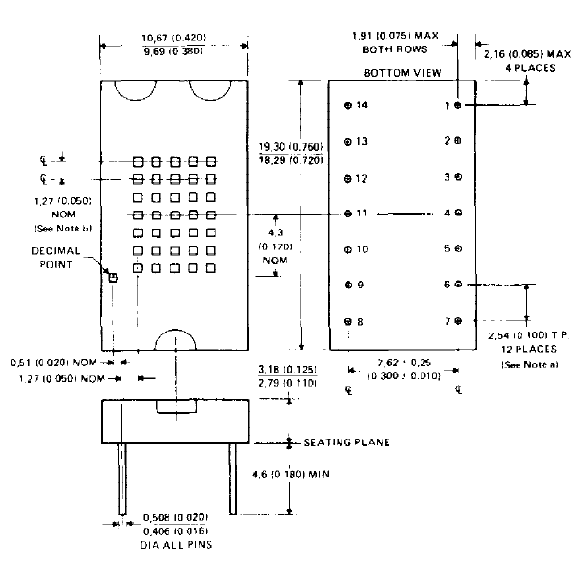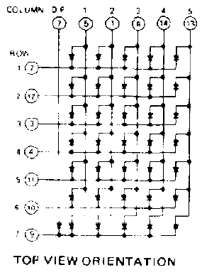
mechanical data
This assembly consists of a display chip mounted on a printed circuit board with a red molded plastic body. Multiple displays may be mounted on 11.43mm (0.450 inch) centers.

Notes:
a. The true position spacing is 2.54mm (0.100 inch) between lead centerlines. Each pin centerline is located within 0.25mm(0.010 inch) of it's true longitudinal position.
b. Vertical and horizontal spacing between centerlines of rows and columns nominally 1.27mm (0.050 inch)
(ALL DIMENSIONS ARE IN MILLIMETERS AND PARENTHETICALLY IN INCHES)

absolute maximum ratings over operating free-air temperature range (unless otherwise noted)
| Reverse Voltage at 25'C Free-Air Temperature | 3V |
| Peak Forward Current, Each Diode | 100mA |
| Average Forward Current (see Note 1): | |
| Each Diode | 10mA |
| Total | 200mA |
| Operating Free-Air Temperature Range | 0' to 70'C |
| Storage Temperature Range | -25'C to 85'C |
operating characteristics of each diode at 25'C free-air temperature (unless otherwise noted)
| PARAMETER | TEST CONDITIONS | MIN | TYP | MAX | UNIT | |
|---|---|---|---|---|---|---|
| Iv | Luminous Intensity (see Note 2) | IF = 10 mA | 40 | 110 | µcd | |
| p | Wavelength at Peak Emission | 660 | nm | |||
| Spectral Bandwidth | 20 | nm | ||||
| VF | Static Forward Voltage | 1.5 | 1.65 | 2 | V | |
| °VF | Average Temperature Coefficient of Static Forward Voltage | IF = 10 mA | -1.4 | mV/C | ||
| TA = 0'C to 70'C | ||||||
| IR | Static Reverse Current | VR = 3V | 10 | µA | ||
| C | Anode to Cathode Capacitance | VR = 0, f = 1Mhz | 80 | pF | ||
NOTES:
1. This average value applies for any 1 ms period
2. Luminous intensity is measured with a light sensor and filter combination that approximates the CIE International Commission on illumination eye response curve.
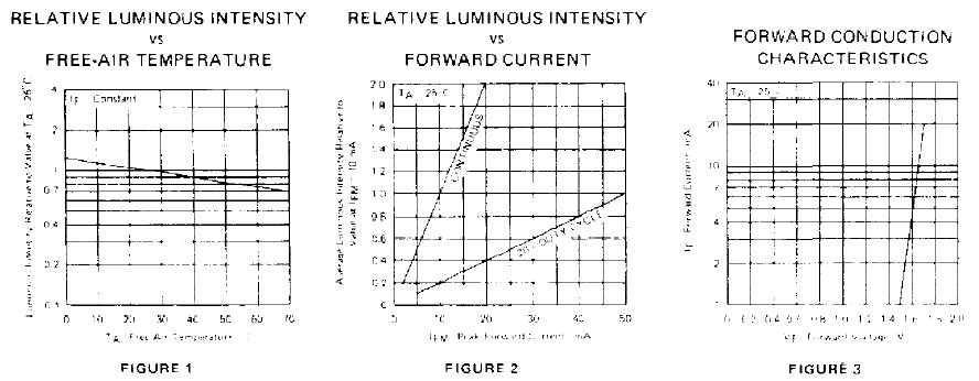
TYPICAL CHARACTERISTICS

Also:
Interested:
Questions: