SX User’s Manual Rev. 3.1
152
© 2000 Scenix Semiconductor, Inc. All rights reserved.
www.scenix.com
Chapter 6 Timers and Interrupts
6.2.1
Prescaler Register
The 8-bit prescaler register is shared between the Watchdog timer and RTCC circuit. It can be
configured to operate as a prescaler for the RTCC circuit or as a postscaler for the Watchdog timer, but
it cannot be used for both purposes at the same time. The selection between the two possible functions
is controlled by the PSA (Prescaler Assignment) bit in the OPTION register.
If the prescaler register is used with the RTCC clock, it reduces the rate at which the RTCC register is
incremented. The instruction cycles or external events being counted are used to increment the
prescaler register, and transitions of a specified bit in the prescaler register are used to increment the
RTCC register.
The rate at which the RTCC register is incremented is reduced by a factor determined by the PS2:PS0
bits in the OPTION register:
6.2.2
Maximum Count
The RTCC counter register is eight bits wide, so it can count up to 256 instruction cycles or external
events. If you use the prescaler register and select a divide-by factor of 256, you can count up to 65,536
instruction cycles or events because the RTCC register is incremented only once per 256 instruction
cycles or events.
The RTCC counter can be configured to trigger an interrupt each time it overflows from FFh to 00h.
To enable this interrupt, clear the RTE_IE bit in the OPTION register. You can have the interrupt
service routine increment a file register (or a set of cascaded file registers), and thereby keep track of
any number of instruction cycles or events.
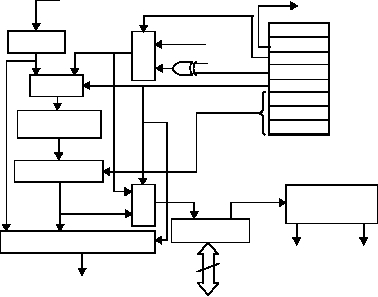
Figure 6-1 RTCC Block Diagram
WDTE (from FUSE Word)
RTCC pin
MUX
8-Bit Prescaler
MUX (8 to 1)
8-Bits
WDT Timeout
Data Bus
WDT
MUX
M
U
X
RTCC
M
U
X
FOSC
RST
RTE_ES
PSA
PS2
PS1
PS0
OPTION
Register
RTCC Rollover
Interrupt
RTE_IE
RTW
RTCC Interrupt Enable
Interrupt
to CPU
Pending Flag
(RTCCOV bit in
T1CNTB Register,
SX48/52BD only)
