© 2000 Scenix Semiconductor, Inc. All rights reserved.
157
SX User’s Manual Rev. 3.1
www.scenix.com
Chapter 6 Timers and Interrupts
5. The interrupt service routine should perform the required task.
6. The interrupt service routine should end with a return-from-interrupt instruction, either RETI or
RETIW.
7. The CPU automatically restores the contents of the program counter, W, STATUS, and FSR reg-
isters; and then resumes normal program execution at the point of interruption. If another inter-
rupt condition occurred during the service routine, it immediately triggers a new interrupt at this
time.
The interrupt response time is always three instruction cycles for an RTCC interrupt or five instruction
cycles for a Multi-Input Wakeup interrupt. This is the amount of time it takes from detection of the
interrupt condition to execution of the first instruction in the interrupt service routine.
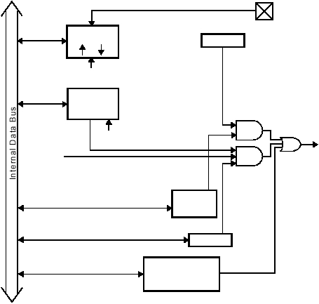
Figure 6-2 is a block diagram showing the internal logic of the interrupt generation circuit. An interrupt
can be generated by either an RTCC rollover or a wakeup/interrupt signal on a Port B pin, if enabled
by the appropriate bit in the OPTION register or STATUS register. A signal on a wakeup/interrupt pin
of Port B generates an interrupt only during normal operation of the device, not in the power down
mode.
Figure 6-2 Interrupt Logic Block Diagram
RTCC
WKED_B
WKED_B
WKPND_B
WKPND_B
From MODE
(MODE = 09/19)
OPTION
RTE_IE
WKEN_B
1 = Ext. Interrupt through Port B
0 = Power Down Mode,
STATUS
Port B PIN
Interrupt
PC
Interrupt Stack
PC
000
Overflow
Device-Specific
Interrupt Sources
(e.g. Timer T1)
Register
PD Flag
From MODE
(MODE = 0A/1A)
no Ext. Interrupt
