A Virtual Peripheral Keyboard Scanner
Introduction
This application note presents programming techniques for scanning a 4x4 keyboard
usually found in both consumer and industrial applications for simple numeric data entry. This
implementation uses the SX s internal interrupt feature to allow background operation of the code
as a virtual peripheral, uses the Parallax demo board and the internal pull-up capability of SX
ports to eliminate the need of any external components.
RB0
RB1
RB2
RB3
RB4
1 2 3
RB5
4 5 6
RB6
7 8 9
RB7
0
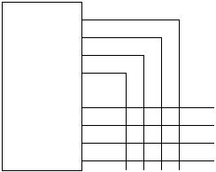
Figure 1 - Keyboard scanner circuit diagram
How the circuit and program work
The circuit is just a simple connection to a keyboard matrix as indicated. Note that only 10
out of 16 positions are used. All 16 positions can be used by simply altering the virtual keyboard
matrix, which assigns value to the key pressed according to their row and column positions. No
external resistors are used due to the capabilities of SX to have internal weak pull up in the range
of 20K. (Note: for Parallax demo board users, the connection to R13 for LED drive must be
clipped off or disconnected since it will create a pull down effect.)
The interrupt code segment uses a state machine approach to scan the keyboard so as not
to tie up the CPU for a long time during keyboard scan.
