 A line following robot using a
video camera as the only sensor with binary image
and video output.
 A line following robot using a
video camera as the only sensor with binary image
and video output.
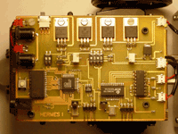
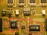
 A custom PCB was designed to house the
Ubicom SX52 and SX28 chips.
 Functions of the SX52:
Functions of the SX28AC/SO:
The main portion of the source code is posted below. It is the code to store the data, calculate deviation between the line center and the main center and send the correction data to the SX28 in order to follow the line.
Sample of Code
;**********************************************************************
; *
; Filename: Hermes I *
; Date: Enero/2003-Mayo/2003 *
; File Version: 4.10 *
; *
;**********************************************************************
; *
; Notes: This program convert a video Image in a binary image, *
; save it in a Sram (AS7C1024), calculate the deviation *
; between the line and the memory center and send the *
; corrections speeds to a SX28 to generate the proper *
; pwm`s *
; *
;**********************************************************************

device SX52,oschs3

In_Odd_Even	= RA.1
In_Vsync 	= RA.2
In_Csync 	= RA.3
Video 		= RA.4
Sincro 		= RA.5

Sw_ON 		= RC.4
WE 		= RC.5
OE 		= RC.6
Ram_Bit 	= RC.7

RAM_X 		= RD
RAM_Y 		= RE

RESET Start

ORG $00
org $0A

RamX_Center 	ds 1
Valor 		ds 1
Divisor 	ds 1
Resultado 	ds 1
Delaycont 	ds 1
Counter 	ds 1

org $10

Puntos 		= $ 		;bank0 variables
Flag_P1 	ds 1
Ini_P1 		ds 1
End_P1 		ds 1
Flag_P2 	ds 1
Ini_P2 		ds 1
Fin_P2 		ds 1
Centro_P1 	ds 1
Centro_P2 	ds 1
Line_Center 	ds 1
Desviation 	ds 1
Speed 		ds 1

Start

	MODE 	$0F 		;Set Mode to allow Direction configuration
	MOV 	!ra,#%10001111 	;Set port A
	MOV 	!rb,#%00000000 	;Set port B
	MOV 	!rc,#%10011100 	;Set port C
	MOV 	!rd,#%00000000 	;Set port D
	MOV 	!re,#%00000000 	;Set port E
	MODE 	$0E 		;Set Mode to allow Pull-Up Resistor configuration
	MOV 	!ra,#%00000000 	;Set pull up resistors
	MOV 	!rb,#%00000000 	;Set pull up resistors
	MOV 	!rc,#%00000000 	;Set pull up resistors
	MOV 	!rd,#%00000000 	;Set pull up resistors
	MOV 	!re,#%00000000 	;Set pull up resistors

bank Puntos
	MOV 	RamX_Center,#$7F ;Define Reference Ram center

	JMP Main

;************************************************************************************************************
;************************************ SUBRUTINAS PAGINA 0 *****************************************
;************************************************************************************************************

;This routine send the binari image to a 256x256 bytes ram memory in binari format and just the odd frame
;in order to use the even frame to calculate speeds, desviations, etc. and draw its in the memory and don`t
;loose pictures

Save_Image

Next_003
	JB In_Odd_even,Next_003 	;Wait the Odd Frame
Next_004
	JB In_Vsync,Next_004 		;Wait the Sart of the frame
	CALL Image_Center_Y 		;Sincronize the Start of the capture in Y
	CALL Store_Ram 			;configure ram enables and port C bits to save data
Next_005
	JB In_Csync,Next_005 		;Wait the H sinc
	CALL Wait_Sync
	CALL Image_Center_X 		;Sincronize the Start of the capture in X
Next_006
	CLRB 	WE			;start to store the binari image
	JB RA.7,Next_007 		;in comparator data
	CLRB 	Ram_Bit
	JMP Next_008
Next_007
	SETB 	Ram_Bit
	NOP
Next_008
	NOP
	SETB 	WE
	INCSZ 	RAM_X 			;check the end of the ram memory in X
	JMP Next_006
	INC 	RAM_Y
Next_009
	CJNE RAM_Y,#$C8,Next_005 	;check the end of the ram memory in Y
Next_010
	CALL Black_Pixel 		;55 lines at the end always in black to draw speeds
	INCSZ 	RAM_X
	JMP Next_010
	INC 	RAM_Y
	CJNE RAM_Y,#$FF,Next_010 	;end of the capture
	RET

;This routine search the ram and locate 2 points, start and end point of the line

Search_Center

	CALL Read_Ram 			;configure ram enables and port C bits to read data
	MOV 	RAM_Y,#$3F 		;move the pointer to the line to search
Next_019
	JB Ram_Bit,Next_022 		;Search the line start
	INC 	RAM_X
	CJE RAM_X,#$FF,Next_020 	;Check no line and jump to stop motors
	JMP Next_019
Next_020
	MOV 	Speed,#$00
	SETB 	RA.6 			;stop left motor
	MOV 	RB,Speed
	nop
	CLRB 	RA.6 			;stop right motor
	RET
Next_022
	MOV 	Ini_P1,RAM_X 		;store the Start point

Next_023
	JNB Ram_Bit,Next_025 		;Search the line end
	INC 	RAM_X
	CJE RAM_X,#$FF,Next_025
	JMP Next_023
Next_025
	MOV 	End_P1,RAM_X 		;store the line end point
	RET