© 2000 Scenix Semiconductor, Inc. All rights reserved.
- 9 -
www.scenix.com
SX48BD/SX52BD/SX52BD75/SX52BD100
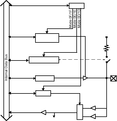
Figure 3-1. Port A Configuration
MODE
RA
RA Data
LVL_A
0 = Output
1 = Hi-Z Input
RD/WR
0 = CMOS Levels
1 = TTL Levels
RD
TTL Buffer
CMOS Buffer
Vdd
Pullup
(~20kW)
Port A PIN
M
U
X
Direction
PLP_A
0 = Pullup Enable
1 = Pullup Disable
Port A INPUT
RD/WR
RD/WR
RD/WR
