© 2000 Scenix Semiconductor, Inc. All rights reserved.
- 24 -
www.scenix.com
SX48BD/SX52BD/SX52BD75/SX52BD100
All interrupts are global in nature; that is, no interrupt has
priority over another. Interrupts are handled sequentially.
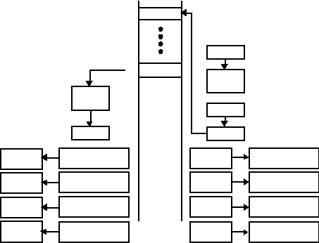
Figure7-2 shows the interrupt processing sequence.
Once an interrupt is acknowledged, all subsequent inter-
rupts are disabled until return from servicing the current
interrupt. The PC is pushed onto the single level interrupt
stack, and the contents of the FSR, STATUS, MODE,
and W registers are saved in their corresponding shadow
registers. The status bits PA2, PA1, and PA0 are cleared
after STATUS has been saved in its shadow register.
The interrupt logic has its own single-level stack and is
not part of the CALL subroutine stack. The vector for the
interrupt service routine is address 0.
Once in the interrupt service routine, the user program
must poll all interrupt pending bits to determine the
source of the interrupt. The interrupt service routine
should clear the corresponding interrupt pending flag.
Normally it is a requirement for the user program to pro-
cess every interrupt without missing any. To ensure this,
the longest path through the interrupt routine must take
less time than the shortest possible delay between inter-
rupts.
Using more than one interrupt, such as multiple external
interrupts or both RTCC and external interrupts, can
result in missed or, at best, jittery interrupt handling
should one occur during the processing of another. When
handling external interrupts, the interrupt routine should
clear at least one pending register bit. The bit that is
cleared should represent the interrupt being handled in
order for the next interrupt to trigger.
Upon return from the interrupt service routine, the con-
tents of PC, FSR, STATUS, MODE, and W registers are
restored from their corresponding shadow registers. The
interrupt service routine should end with instructions such
as RETI or RETIW. RETI pops the interrupt stack and the
special shadow registers used for storing W, STATUS,
MODE, and FSR (preserved during interrupt handling).
RETIW behaves like RETI but also adds W to RTCC.
The interrupt return instruction enables the global inter-
rupts.
If a MIWU interrupt occurs during a pre-existing interrupt
service routine, the MIWU interrupt flag is set immedi-
ately, and the MIWU interrupt is serviced upon comple-
tion of the pre-existing interrupt service routine.
Figure 7-2. Interrupt Processing
Interrupt
PC
RETI
PC
PC
W
Register
000h
Address 000h
Program
Memory
Interrupt
Service
Routine
STATUS
Register
FSR
Register
W
Shadow Register
STATUS
Shadow Register
FSR
Shadow Register
W
Register
STATUS
Register
FSR
Register
W
Shadow Register
STATUS
Shadow Register
FSR
Shadow Register
Stack
Interrupt
Stack
Note:The interrupt logic has its own single-level
stack and is not part of the CALL subroutine stack.
MODE
Register
MODE
Shadow Register
MODE
Register
MODE
Shadow Register