© 2000 Scenix Semiconductor, Inc. All rights reserved.
- 23 -
www.scenix.com
SX48BD/SX52BD/SX52BD75/SX52BD100
7.0
INTERRUPT SUPPORT
The device supports both internal and external maskable
interrupts. The internal interrupt is generated as a result
of the RTCC rolling over from FFh to 00h. This interrupt
source has an associated enable bit located in the
OPTION register and pending flag bit in the Timer T1
Control B register. In addition, timers T1 and T2 each
have three interrupt sources associated with counter
overflow, compare match, and input capture.
Port B provides the source for eight external software
selectable, edge sensitive interrupts, when the device is
not in the power down mode. These interrupt sources
share logic with the Multi-Input Wakeup circuitry. The
WKEN_B register allows interrupt from Port B to be indi-
vidually enabled or disabled. Clearing a bit in the
WKEN_B register enables the interrupt on the corre-
sponding Port B pin. The WKED_B selects the transition
edge to be either positive or negative. The WKEN_B and
WKED_B registers are set to FFh upon reset. Setting a
bit in the WKED_B register selects the falling edge while
clearing the bit selects the rising edge on the correspond-
ing Port B pin.
The WKPND_B register serves as the external interrupt
pending register.
The WKPND_B register comes up with a random value
upon reset. The user program must clear the WKPND_B
register prior to enabling the interrupt.
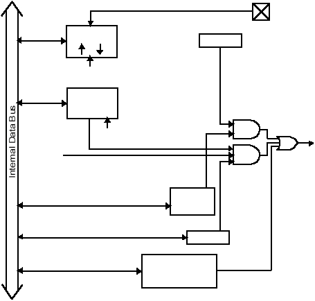
Figure 7-1. Interrupt Structure
RTCC
WKED_B
WKED_B
WKPND_B
WKPND_B
From MODE
(MODE = 09/19)
OPTION
RTE_IE
WKEN_B
1 = Ext. Interrupt through Port B
0 = Sleep Mode, no Ext. Interrupt
STATUS
Port B PIN
Interrupt
PC
000
Overflow
Device-Specific
Interrupt Sources
(e.g. Timer T1)
Register
PD Flag
From MODE
(MODE = 0A/1A)
PC, STATUS, FSR, W, MODE
Interrupt Stack
