64
www.ubicom.com
IP2022 Data Sheet
5.6.9
SPI
Hardware
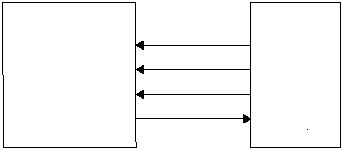
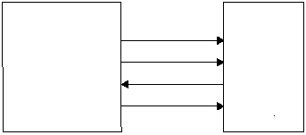
Figure 5-14 shows example circuits to connect the
SERDES in SPI mode. Table 5-10 shows the SPI signal to
port pin usage.
Software
To set up a SERDES unit for the SPI protocol, set up the
clock with opposing phases for transmit and receive by
programming the SUBM1:0 field of the SxMODE register.
If in slave mode, specify an external clock. If in master
mode, specify an internal clock. In slave mode, software
must check if the designated slave select line is activated
before responding. In master mode, software must set the
designated slave select pin (GPIO) to the active level
before enabling the SERDES unit.
To operate in SPI mode, once the transmit and receive bit
counts in the configuration registers are programmed with
non-zero values, the SERDES unit begins shifting
operations on the programmed clock edges. Caution must
be exercised to program them quickly to avoid losing any
data. If SxTBuf is not written to since the last transmit shift
register reload, the SERDES will still be expecting to
operate correctly, although it’s DataOut will be undefined
for the next entire transfer.
Figure 5-14 SPI Interface Examples
SPI
Master
SxCLK
IP2022
(SPI Slave)
515-095a.eps
SxTXP(DO)
SCLK
DI
SxRXD(DI)
DO
SxRXP
SS
OR
SPI
Slave
SxCLK
IP2022
(SPI Master)
SxTXP(DO)
SCLK
DI
SxRXD(DI)
DO
GPIO
SS
SCLK
DO
DI
SS
SCLK
DO
DI
SS
Table 5-9 IP2022 SPI Master Interface Signal Usage
SPI Device
Signal Name
IP2022 SPI
Signal Name
SERDES
Signal Name
SERDES1
Pin Name
SERDES2
Pin Name
Direction
Description
SCLK
SCLK
SxCLK
RE0
RF4
Output
Serial clock output in master
mode, input in slave mode
DO
DI
SxRXD
RE3
RF7
Input
Receive data
DI
DO
SxTXP
RE5
RF1
Output
Transmit data
SS
SS
GPIO
RE1
RF5
Output
Slave select pin used in slave
mode only (Master select handled
by software)

