IP2022 Data Sheet
www.ubicom.com
63
5.6.8
UART
For UART operation, two internal divide-by-16 circuits are
used. Based on the clock source (either internal or
external), the receive section and the transmit section use
two divided-by-16 clocks that potentially can be out of
phase. This is due to the nature of the UART bus
transfers. The receive logic, based on the 16x bit clock
(the clock source chosen by user), will sample the
incoming data for an falling edge. Once the edge is
detected, the receive logic counts 8 clock cycles and
samples the number of bits specified in the SxRCNT
register using the bit clock (which is obtained by dividing
the clock source by 16).
Hardware
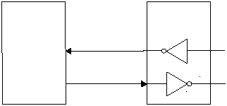
Figure 5-13 shows an example circuit to connect the
SERDES in UART mode. Table 5-8 shows the UART
signal to port pin usage.
Software
To set up a SERDES unit for UART mode, select UART
mode in the PRS3:0 bits of the SxMODE register. This
causes the data to be clocked in after a valid start bit is
detected. Make sure that the polarity selected by the
RPOREV bit in the SxRCFG register and the TPOREV bit
in the SxTCFG register match the polarity provided by the
RS-232 transceiver. (Most of them are inverted.) Make
sure the bit order is compatible with the data format (RS-
232 uses LSB-first bit order). The receiver uses 16X
oversampling, so select a SERDES clock divisor (see
Section 7.1.17 for information on the SxTMRH/L
registers) that is 16 times the desired baud rate.
To operate in UART mode, depending on the application,
either transmit or receive can be performed first. In both
cases, the configuration register needs to be programmed
with a bit count that is appropriate for the format. The bit
count depends on the number of data bits, stop bits, and
parity bits. The start bit is included in the bit count. The
receiver does not check for the presence of stop bits. To
detect framing errors caused by missing stop bits,
increase the receiver’s bit count (i.e. the RXSCNT field in
the SxRCFG register) and test the trailing bit(s) in
software.
Figure 5-13 UART Interface Example
RS-232
Transceiver
SxRXD
IP2022
515-094.eps
SxTXP
RxIN
TxOUT
RS-232
RxOUT
TxIN
Table 5-8 UART Interface Signal Usage
UART
Signal Name
SERDES
Signal Name
SERDES1
Pin Name
SERDES2
Pin Name
Direction
Description
RXD
SxRXD
RE3
RF7
Input
Receive data
TXD
SxTXP
RE5
RF1
Output
Transmit data
