IP2022 Data Sheet
www.ubicom.com
61
5.6.7
USB
The SERDES provide support for USB revision 1.1 host
and device modes of operation.
Hardware
To set up a SERDES unit for USB mode, the received data
output of the USB transceiver should be connected to
SxRXD. The VP and VM pins of the transceiver are
connected to the SxRXP and SxRXM pins to allow
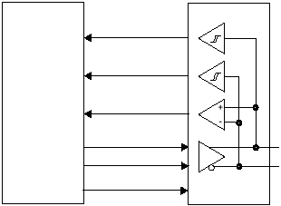
detection of the EOP condition. Figure 5-12 shows the
connections required between an external USB
transceiver and the IP2022. Table 5-6 shows the mapping
of USB signals to the SERDES pins.
Software
The SxMODE register must be programmed with values
for a recovered clock, and the PLL clock multiplier must be
programmed to generate the appropriate frequency. Table
5-7 sows the PLL clock required for the low and full
speeds of USB. For example, it can be programmed at 48
MHz for full speed with a divisor of zero (=1). A divisor of
8 will make it suitable for low-speed operation. The
synchronization pattern must be programmed into the
SxRSYNC register to trigger an interrupt when a packet is
received. Table shows the PLL clock frequencies which
are required for USB operation. Alternatively, an external
clock source can be applied to the SxCLK pin at the
appropriate frequency.
To operate in USB mode, software must perform the
following functions:
•
CRC generation and checking (can be done using the
LFSR, Section 5.9).
•
Detecting reset of the device function, which is indi-
cated by 10 milliseconds of a single-ended zero (SE0)
condition on the bus.
•
Detecting the suspend state, which is indicated by
more than 3 milliseconds of idle. Software must make
sure that the suspend current of 500 µA will be drawn
after 10 milliseconds of bus inactivity.
•
Formation of the USB packet by putting the sync, pid,
and data into the transmit register and setting the
proper count.
The synchronization pattern register (SxRSYNC) is used
for detecting bit patterns that signal the start of a frame.
For USB, this register is loaded with 10000000. The
incoming data stream is compared to the synchronization
pattern. Once a match is found, an internal counter is set
to zero and data is shifted into a shift register. The
synchronization matching operation is then disabled until
an
EOP
condition
is
detected,
because
the
synchronization pattern potentially could be embedded in
the data stream as valid data.
The clock/data separation circuit performs NRZI
decoding, after which, bit unstuffing is performed. This
means every bit after a series of six consecutive ones is
dropped.
Note: While configured for USB mode, the SERDES
cannot be configured to interrupt on carrier status
(RxCRS, SxRCNT bit 5, see Section 7.1.13)
Figure 5-12 USB Interface Example
PDIUSBP11A
SxRXD
IP2022
515-034b.eps
SxRXM
SxTXP
SxTXM
D+
D-
USB Bus
SxRXP
RCV
VM
VPO
VMO
VP
SxOE
OE
