IP2022 Data Sheet
www.ubicom.com
59
5.6.6
10base-T Ethernet
Hardware
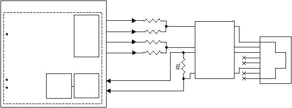
To set up a SERDES unit for 10Base-T Ethernet, the input
data from a differential line receiver or on-board
comparator is connected to the SxRXD input. The signals
designated Tx+, Tx-, TxD+, and TxD- correspond to the
SxTXP, SxTXM, SxTXPE, and SxTXME pins of the
corresponding serializers/deserializers. These pins are
connected to an RJ45 jack through a transformer with
terminations. Figure 5-11 shows an example circuit.
RTXPE, RTXME, RTXP, RTXM and RL values vary
depending on the Ethernet magnetics used. Please refer
to IP2022 Native Ethernet application notes for more
details.
For 10Base-T Ethernet operation, each SERDES is
equipped with a squelch circuit for discriminating between
noise, link pulses, and data. Link pulses are sent
periodically to keep the channel open when no data is
being transmitted. The squelch circuit handles link pulse
detection, link pulse polarity detection, carrier sense, and
EOP detection.
Software
The SxMODE register must be programmed for a
recovered clock, and the PLL clock multiplier must be
programmed for an appropriate speed. For example, it
can be programmed to be 80 MHz for 8× oversampling.
The received data stream is used, together with the clock
recovery circuit, to recover the original transmit clock and
data.
Note: The minimum core clock frequency required in
10base-T mode is 80MHz.
Software must perform the following functions:
•
Polarity detection and reversal.
•
Carrier sense.
•
Jabber detection.
•
Link integrity test and link pulse generation.
•
Random back off in case of collision.
•
When a collision is detected, sending a 32-bit jam se-
quence. Collisions can be detected by either receiv-
ing an RXXCRS interrupt or by setting the bit count to
7 and then received a RXBF interrupt while transmit-
ting.
•
Formation of Ethernet packet by putting the preamble,
sfd, destination address, source address, length/type,
MAC client data into the transmit buffer. Frame check
computation can be done in software or through the
LFSR units (see Section 5.9).
•
MAC layer functions.
Figure 5-11 Ethernet Interface Example
Clock recovery
Rx+
Rx-
Manchester
decoding
coding
Serializer/Deserializer
RJ45
Data
Encoder
Data
Decoder
Manchester
IP2022
Rtxpe
Squelch
SxRX-
SxRX+
SxTXPE
Ethernet
Magnetics
(LPF required)
SxTXM
SxTXME
SxTXP
TxD+
TxD-
Tx-
Tx+
Rtxme
Rtxm
Rtxp
515-064c.eps
