56
www.ubicom.com
IP2022 Data Sheet
SxTBUFH/SxTBUFL Registers
16-bit register pair for loading data to be transmitted. The
TXBE bit in the SxINTF register indicates when the data
has been transmitted and the register is ready to be
loaded with new data. If the corresponding bit in the
SxINTE register is set, an interrupt is generated.
5.6.3
SERDES Configuration
The synchronization pattern register (SxRSYNC) is used
for USB and 10Base-T protocols for detecting bit patterns
that signal the start of a frame. For USB, this register is
loaded with 10000000, while for 10Base-T, it is 11010101
(also called the SFD, start of frame delimiter). The
incoming data stream, after passing through the polarity
inversion logic (which can be turned on or off under
software control) is compared to the synchronization
pattern. Once a match is found, an internal counter is set
to zero and data is shifted into a shift register. The
synchronization matching operation is then disabled until
an
EOP
condition
is
detected,
because
the
synchronization pattern potentially could be embedded in
the data stream as valid data.
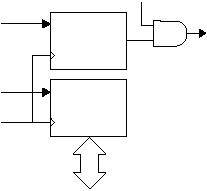
Figure 5-8 shows the receive data paths. Software
prepares a SERDES unit to receive data by programming
the receive shift count register (SxRCFG) and the clock
select bits in the SxMODE register appropriately for the
selected protocol. The SxRCFG register is copied to an
internal counter, and when that number of bits of data has
been received, the received data is loaded into the
SxRBUF register.
Figure 5-8 Receive Data Paths
In 10Base-T, GPSI, or USB mode, when an EOP is
detected the SxRCNT register is loaded with the number
of bits actually received, the EOP bit of the SxINTF
register is set, and the data bits are loaded into the
SxRBUF register. The RXBF bit in the SxINTE register
can be set to enable an interrupt on this event.
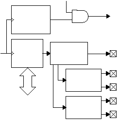
Figure 5-9 shows the transmit data paths. The SxTXP and
SxTXM pins correspond to the differential outputs of the
USB or Ethernet bus. Other serial protocols require only
one output pin, which is SxTXP by default.
The SxTXP and SxTXM pins have high current outputs for
driving Ethernet magnetics directly without the use of
transceivers.
When the clock select register is programmed with the
value
for
10Base-T,
the
transmit
pre-emphasis
requirement enables the SxTXPE and SxTXME outputs,
which have a 50ns-delayed version of the transmit output
that is resistively combined outside the chip before driving
the magnetics.
Figure 5-9 Transmit Data Paths
The data encode block performs polarity inversion, if
necessary, then in 10Base-T mode it performs
Manchester encoding. In USB bus mode, it performs bit
stuffing and then NRZI encoding. Bit stuffing means that
after six consecutive ones, a zero bit is inserted. The
active low SxOE pin is used to enable the USB transceiver
for transmission. Otherwise, this pin is held high. For
10Base-T, the output pins of the serializer are driven low
when not transmitting. The encode block is bypassed for
all other protocols.
515-004.eps
EOP
Receive
Count
Register
(SxRCNT)
Receive
Data
Receive
Clock
Receive
Buffer
Register
(SxRBUF)
Data Bus
RXBF
Receive
Interrupt
515-018.eps
Transmit
Configuration
Register
(SxTCFG)
Transmit
Clock
SxOE
Data
Encoder
Transmit
Buffer
Register
(SxTBUF)
Data Bus
SxTXPE
Pre-Emphasis
EOP
Generator
SxTXME
SxTXP
SxTXM
TXBE, TXEOP
Transmit
Interrupt

