50
www.ubicom.com
IP2022 Data Sheet
5.3
Real-Time Timer
The Real-Time Timer is an 8-bit timer intended to provide
a periodic system wake-up interrupt. Unlike the other
peripherals (except the Watchdog Timer and Port B
interrupts), the Real-Time Timer continues to function
when the system clock is disabled. For those applications
which spend much of their time with the OSC clock
oscillator turned off to conserve power, there are 5
available mechanisms to exit this mode: external reset
(RST pin), reset from the Watchdog Timer, reset from
Brown-out, interrupt from a Port B input, and interrupt
from the Real-Time Timer. By using an interrupt rather
than reset, more of the CPU state is preserved and some
reset procedures such as initializing the port direction
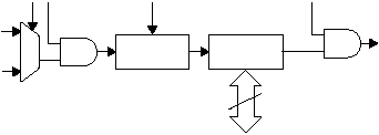
registers can be skipped. Figure 5-4 shows the Real-Time
Timer logic.
When the RTTMR register counts up to FF and rolls over
to 00, the RTIF flag in the RTCFG register will be set, and
an interrupt will occur if the RTIE and RTEN bit are set
(see RTCFG register description in Section 7.1.9). To
clear the interrupt, either the RTIE or RTEN bit should be
cleared, and then the RTIF flag be cleared.
Note: If RTIF is not cleared after disabling the Real-Time
Timer interrupt (RTIE = 0) or disabling the Real-Time
Timer (RTEN = 0), it is assumed that another interrupt has
occured, and the interrupt will occur on the next return, or
when GIE is set (enabling nested interrupts - see Section
3.7.2).
The real-time timer is readable and writable as the
RTTMR register. The control and status register for the
timer is the RTCFG register, as described in Section 7.1.9.
The RTEOS bit (XCFG bit 5, see Section 7.1.26) selects
the sampling mode for the external input. If the RTEOS bit
is set, the external input is over-sampled with the system
clock. The CPU can always read the value in the RTTMR
register, however, the system clock must be at least twice
the frequency of the external input. If the system clock
source is changed to RTCLK or turned off, then the
RTEOS bit must be clear for the Real-Time Timer to
function.
Note: if the RTEOS bit is cleared, expect a 3 cycle system
clock delay for the overflow interrupt, due to
synchronization circuitry.
If the RTEOS bit is clear then the external input directly
clocks the Real-Time Timer (i.e. RTCLK is not
oversampled). The Real-Time Timer will always function
whether the clock input is synchronous or asynchronous.
However, the CPU cannot reliably read the value in the
RTTMR register unless the RTCLK clock is synchronous
to the system clock.
If the value in the RTTMR register does not need to be
used by the CPU (i.e. only the interrupt flag is of interest)
then the RTEOS bit can be clear (i.e. RTCLK not
oversampled) which allows the Real-Time Timer to
function for any configuration of the system clock.
If the value in the RTTMR register needs to be used by the
CPU, but the Real-Time Timer is not required to function
when the system clock is set to RTCLK or turned off, then
the RTEOS bit should be set to ensure the CPU can
reliably read the RTTMR register.
If the value in the RTTMR register needs to be used by the
CPU and the Real-Time Timer is required to function
when the system clock is set to RTCLK or off, then
software must change the RTEOS bit when changing the
system clock source. To read the RTTMR register when
the system clock is not synchronous to the RTCLK, the
RTEOS bit must be set to ensure reliable operation.
Before the system clock is changed to RTCLK or turned
off, the RTEOS bit must be clear (i.e. RTCLK not
oversampled) for the Real-Time Timer to continue to
function.
Note: When using development tools in single stepping
mode, the RTSS bit must be cleared, otherwise the
counter will behave erratically.
Figure 5-4 Real-Time Timer Block Diagram
515-015a.eps
RTTMR
Register
RTIE
RTIF
15-Bit
Prescaler
OSC
Clock
RTCLK
RTEN
RTPS 3:0
RTSS
Data Bus
8
