IP2022 Data Sheet
www.ubicom.com
79
5.9.9
RESx Registers
The five RESx registers hold the 40-bit residue used in the
LFSR operation. The ML_OUT bit controls the mapping of
the residue register to the RESx registers, as shown in
Figure 5-23. The residue register can be initialized to all
ones by setting the SET_RES bit in the LFSRCFG1
register.
5.9.10 RESCMPx Registers
The four RESCMPx registers hold a 32-bit value for
comparison with the contents of the residue register. After
an LFSR operation is completed, the CMP_RES bit in the
LFSRCFG1 register indicates whether the result of the
operation matched the 32-bit value. When the ML_OUT
bit in the LFSRCFG3 register is clear, bits 39:8 of the
residue register are compared against bits 0:31 of the
RESCMP register. When ML_OUT is set, bits 0:31 of the
residue register are compared against bits 0:31 of
RESCMP.
5.10 Parallel Slave Peripheral
The Parallel Slave Peripheral allows the IP2022 to
operate as an 8- or 16-bit slave to an external device,
much like a memory chip. Alternate functions of Port C
and Port D are used for transferring data, and alternate
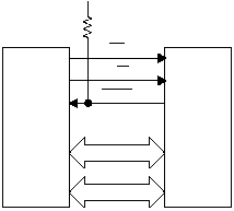
functions of Port B are used for control signals. Figure 5-
28 shows the connections between an external master
and the Parallel Slave Peripheral interface.
Figure 5-28 Parallel Slave Peripheral
To read or write through the Parallel Slave Peripheral
interface, the external master asserts the chip select (CS)
signal low. This signal is an alternate function of port pin
RB7. The direction of transfer is indicated by the R/W
signal, which is an alternate function of port pin RB6.
When the R/W signal is high, the master is reading from
the slave. When the R/W signal is low, the master is
writing to the slave.
Optionally, a HOLD signal may be enabled as an alternate
function of port pin RB5. Assertion of HOLD indicates to
the external master that the Parallel Slave Peripheral
interface is not ready to allow the data transfer to
complete. The HOLD signal is driven like an open-
collector signal, i.e. low when asserted and high-
impedance when not asserted. When the CS signal is not
asserted (i.e. the IP2022 is not selected), the HOLD signal
is in high-impedance mode. The HOLD signal should
have an external pullup resistor (R1 = 10K
W
is
recommended). The CS signal must not be allowed to
float.
When CS is asserted, an interrupt is generated and HOLD
(if enabled) is automatically asserted. If the data transfer
is a write from the external master, software reads the Port
C, Port D, or both. If the data transfer is a read, software
writes the data to the port or ports. Finally, if HOLD is
asserted, software releases assertion of HOLD by writing
to the PSPRDY bit in the PSPCFG register.
The Parallel Slave Peripheral does not generate
interrupts by itself. Software is required to enable port pin
RB7 (the CS input) as a falling-edge interrupt input for the
Parallel Slave Peripheral to function. The CS signal must
go high, then back low, for each data transfer. RB6 (the
R/W input) must also be configured as an input. The
setting in the RBDIR register for RB5 (the HOLD output)
is overridden by the programming of the Parallel Slave
Peripheral.
5.10.1 PSPCFG Register
The PSPCFG register is used to enable the Parallel Slave
Peripheral, select which ports are used for data transfer,
enable the HOLD output, and release the HOLD output
when the data transfer is ready to complete.
•
PSPEN2—set to enable Port D for data transfer, clear
to disable. (If this bit is set, the Parallel Slave Periph-
eral overrides the RDDIR register.)
External
Master
Data
Data
HOLD
IP2022
Slave
515-033.eps
R/W
CS
RB7
RB6
RB5
IOVDD
R1
RD7:0
RC7:0
7
6
5
4
3
0
PSPEN2 PSPEN1 PSPHEN PSPRDY
Reserved
Table 5-17 PSPCFG Register
