70
www.ubicom.com
IP2022 Data Sheet
5.6.12 SERDES Protocol-Specific
Considerations
UART Interface
To set up a SERDES unit for UART mode, select UART
mode in the PRS3:0 bits of the SxMODE register. This
causes the data to be clocked in after a valid start bit is
detected. Make sure that the polarity selected by the
RPOREV bit in the SxRCFG register and the TPOREV bit
in the SxTCFG register match the polarity provided by the
RS-232 transceiver. (Most of them are inverted.) Make
sure the bit order is compatible with the data format (RS-
232 uses LSB-first bit order). The receiver uses 16X
oversampling, so select a clock divisor that is 16 times the
desired baud rate.
To operate in UART mode, depending on the application,
either transmit or receive can be performed first. In both
cases, the configuration register needs to be programmed
with a bit count that is appropriate for the format. The bit
count depends on the number of data bits, stop bits, and
parity bits. The start bit is included in the bit count. The
receiver does not check for the presence of stop bits. To
detect framing errors caused by missing stop bits,
increase the receiver’s bit count (i.e. the RXSCNT field in
the SxRCFG register) and test the trailing bit(s) in
software.
SPI Protocol
To set up a SERDES unit for the SPI protocol, set up the
clock with opposing phases for transmit and receive by
programming the SUBM1:0 field of the SxMODE register.
If in slave mode, specify an external clock. If in master
mode, specify an internal clock. In slave mode, software
must check if the designated slave select line is activated
before responding. In master mode, software must set the
designated slave select pin to the active level before
enabling the SERDES unit.
To operate in SPI mode, once the transmit and receive bit
counts in the configuration registers are programmed with
non-zero values, the SERDES unit begins shifting
operations on the programmed clock edges. Caution must
be exercised to program them quickly to avoid losing any
data.
USB 1.1 Protocol
To set up a SERDES unit for USB mode, the received data
output of the USB transceiver should be connected to
SxRXD. The VP and VM pins of the transceiver are
connected to the SxRXP and SxRXM pins to allow
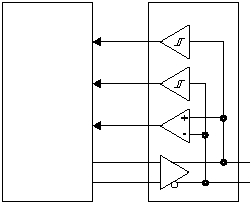
detection of the EOP condition. Figure 5-16 shows the
connections required between an external USB
transceiver and the IP2022.
Figure 5-16 USB Interface Example
The SxMODE register must be programmed with values
for a recovered clock, and the PLL clock multiplier must be
programmed to generate the appropriate frequency. For
example, it can be programmed at 48 MHz for full speed
with a divisor of zero (=1). A divisor of 8 will make it
suitable for low-speed operation. The synchronization
pattern must be programmed into the SxRSYNC register
to trigger an interrupt when a packet is received.
To operate in USB mode, software must perform the
following functions:
•
CRC generation and checking.
•
Detecting reset of the device function, which is indi-
cated by 10 milliseconds of a single-ended zero (SE0)
condition on the bus.
•
Detecting the suspend state, which is indicated by
more than 3 milliseconds of idle. Software must make
sure that the suspend current of 500 µA will be drawn
after 10 milliseconds of bus inactivity.
•
Formation of the USB packet by putting the sync, pid,
and data into the transmit register and setting the
proper count.
10Base-T Ethernet Protocol
To set up a SERDES unit for 10Base-T Ethernet, the input
data from a differential line receiver or on-board
comparator is connected to the SxRXD input. The signals
designated Tx+, Tx-, TxD+, and TxD- correspond to the
SxTXP, SxTXM, SxTXPE, and SxTXME pins of the
corresponding serializers/deserializers. These pins are
connected to an RJ45 jack through a transformer with
terminations.
PDIUSBP11A
SxRXD
IP2022
515-034.eps
SxRXM
SxTXP
SxTXM
D+
D-
USB Bus
SxRXP
