38
www.ubicom.com
IP2022 Data Sheet
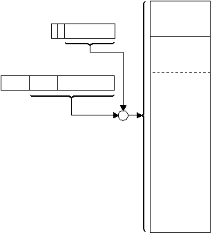
This stack addressing mechanism is completely
independent from the hardware stack used for subroutine
call and return.
When a pop instruction is used with the indirect-with-
offset addressing mode, the address calculation for the
“fr” operand is made using the value in the SPH/SPL
register before the automatic increment, even though the
stack operand itself is addressed using the value after the
automatic increment.
Figure 4-6 Indirect-with-Offset Mode, Stack Pointer
4.2
Instruction Set
The instruction set consists entirely of single-word (16-bit)
instructions, most of which can be executed at a rate of
one instruction per clock cycle, for a throughput of up to
100 MIPS when executing out of program RAM.
Assemblers may implement additional instruction
mnemonics for the convenience of programmers, such as
a long jump instruction which compiles to multiple IP2022
instructions for handling the page structure of program
memory. Refer to the assembler documentation for more
information
about
any
instruction
mnemonics
implemented in the assembler.
4.2.1
Instruction Formats
There are five instruction formats:
•
Two-operand arithmetic and logical instructions
•
Immediate-operand arithmetic and logical instructions
•
Jumps and subroutine calls
•
Bit operations
•
Miscellaneous instructions
Figure 4-7 shows the two-operand instruction format. The
two-operand instructions perform an arithmetic or logical
operation between the W register and a data memory
location specified by the “fr” field. The D bit indicates the
destination operand. When the D bit is clear, the
destination operand is the W register. When the D bit is
set, the destination operand is specified by the “fr” field.
There are some exceptions to this behavior. The multiply
instructions always load the 16-bit product into the MULH
and W registers. The MULH register receives the upper 8
bits, and the W register receives the lower 8 bits.
Traditionally single-operand instructions, such as
increment, are available in two forms distinguished by the
D bit. When the D bit is clear, the source operand is
specified by the “fr” field and the destination operand is
the W register. When the D bit is set, the data memory
location specified by the “fr” field is both the source and
destination operand.
Also, there are a few cases of unrelated instructions, such
as clr and cmp, which are distinguished by the D bit.
Figure 4-8 shows the immediate operand instruction
format. In this format, an 8-bit literal value is encoded in
the instruction field. Usually the W register is the
destination operand, however this format also includes
instructions that use the top of the stack or a special-
purpose register as the destination operand.
Figure 4-9 shows the format of the jump and subroutine
call instructions. 13 bits of the entry point address are
515-027.eps
128
Special-Purpose
Registers
SPH Register
SPL Register
7
0
n
0
n
7
n n n n n n n
X
3
4
7
X X X n n n
0
9-Bit "fr" Field
from Instruction
1
8
1 mmmmmmm
0
+
7
6
3840 Bytes
Data Memory
128
Global Registers
15
10
9
8
0
Opcode
D
“fr” Field
Figure 4-7 Two-Operand Instruction Format
15
8
7
0
Opcode
8-Bit Literal (“#lit8”)
Figure 4-8 Immediate-Operand Instruction Format
