36
www.ubicom.com
IP2022 Data Sheet
4.1.1
Pointer Registers
When an addition or increment instruction (i.e. add,
addc, inc, incsz, or incsnz) on the low byte of a
pointer register (i.e. IPL, DPL, SPL, or ADDRL) generates
a carry, the high part of the register is incremented. For
example, if the IP register holds 0x00FF and an inc ipl
instruction is executed, the register will hold 0x0100 after
the instruction. When a subtraction or decrement
instruction (i.e. sub, subc, dec, decsz, or decsnz)
generates a borrow, the high part of the register is
decremented.
Because
carry
and
borrow
are
automatically handled, the addc and subc instructions
are not needed for arithmetic on pointer registers.
4.1.2
Direct Addressing Mode
Figure 4-2 shows the direct addressing mode used to
reference the special-purpose registers. Seven bits from
the “fr” field allow addressing up to 128 special-purpose
registers. (Not all 128 locations in this space are
implemented in the IP2022; several locations are
reserved for future expansion.)
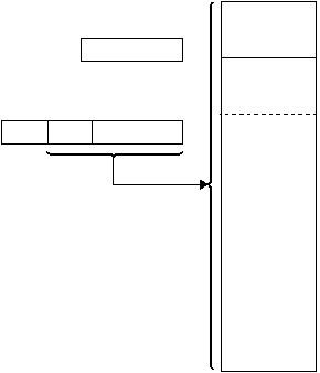
Figure 4-2 Direct Mode, Special-Purpose Registers
The following code example uses direct mode.
Figure 4-3 shows the direct addressing mode used to
reference the global registers. This mode is distinguished
from the mode used to access the special-purpose
registers with bit 7 of the “fr” field. Because these registers
have this additional addressing mode not available for the
other data memory locations, they are especially useful
for holding global variables and frequently accessed data.
Figure 4-3 Direct Mode, Global Registers
4.1.3
Indirect Addressing Mode
The indirect addressing mode is used when all of the bits
in the “fr” field are clear. The location of the operand is
specified by a 12-bit pointer in the IPH and IPL registers.
The upper four bits of the IPH register are not used.
Addresses from 0x000 to 0x01F cannot be accessed
reliably with this addressing mode, therefore it must not
be used for this purpose. (Direct mode should be used
instead.) Figure 4-4 shows indirect mode.
Figure 4-4 Indirect Mode
mov
w,0x0012 ;load W with the contents of
;the memory location at 0x0012
;(the DATAL register)
515-007.eps
128
Special-Purpose
Registers
7
0
9-Bit "fr" Field
from Instruction
0
8
0 n n n n n n n
0
7 6
515-008.eps
128
Global Registers
7
0
9-Bit "fr" Field
from Instruction
0
8
1 n n n n n n n
0
7 6
515-009.eps
128
Special-Purpose
Registers
3840 Bytes
Data Memory
IPH Register
IPL Register
7
0
n
0
n
7
n n n n n n n
X
3
4
7
X X X n n n
0
9-Bit "fr" Field
from Instruction
0
8
0 0 0 0 0 0 0 0
0
128
Global Registers
