IP2022 Data Sheet
www.ubicom.com
25
3.7.1
External Connections
Figure 3-17 shows the connections for driving the OSC or
RTCLK clock sources with an external signal. To drive the
OSC clock source, the external clock signal is driven on
the OSC1 pin and the OSC2 pin is left open. The external
clock signal driven on the OSC1 pin may be any
frequency up to 150 MHz. To drive the RTCLK clock
source, the external clock signal is driven on the RTCLK1
input and the RTCLK2 output is left open. The external
clock signal driven on the RTCLK1 pin may be any
frequency up to 100 MHz.
Figure 3-17 External Clock Input
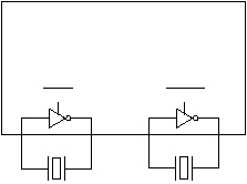
Figure 3-18 shows the connections for attaching an
external crystal to the OSC or RTCLK oscillator. For the
OSC oscillator, a crystal between 1 MHz and 6 MHz is
connected across the OSC1 and OSC2 pins. For the
RTCLK oscillator, a 32.768 kHz crystal is connected
across the RTCLK1 and RTCLK2 pins. No external
capacitors are required.
For proper operation of the crystal or resonator, the total
printed circuit board trace length for the OSC1 and OSC2
signals must be kept to less than 1 inch (2.5 cm) each,
and the capacitive loading must be kept to less than 3
picofarads. Routing should be direct and no vias should
be used.
Figure 3-18 Crystal Connection
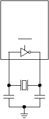
Figure 3-19 shows the connections for attaching an
external ceramic resonator to the OSC oscillator. The
frequency of the resonator must be between 1 MHz and 6
MHz. The value of the external capacitors C1 and C2 is 5
pF. The RTCLK oscillator may not be used with an
external ceramic resonator.
Figure 3-19 Ceramic Resonator Connection
RTCLK1 RTCLK2
Externally
Generated Clock
Open
515-024.eps
IP2022
OSC1
OSC2
Externally
Generated Clock
Open
515-025.eps
Crystal
Crystal
IP2022
OSC1
OSC2
XTAL
RTCLK1
RTCLK2
RTCLK
C1
515-039.eps
C2
Ceramic
Resonator
IP2022
OSC1
OSC2
XTAL

