IP2022 Data Sheet
www.ubicom.com
17
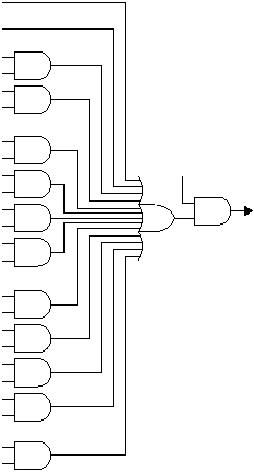
Figure 3-8 System Interrupt Logic
3.5.1
Interrupt Processing
There is one interrupt vector held in the INTVECH and
INTVECL registers, which is reprogrammable by
software. When an interrupt is taken, the current PC is
saved in the IPCH and IPCL registers. On return from
interrupt (i.e. execution of the reti instruction), the PC is
restored from the IPCH and IPCL registers. Optionally, the
reti instruction may also copy the incremented PC to
the INTVECH and INTVECL registers before returning.
This has the effect of loading the INTVECH and INTVECL
registers with the address of the next instruction following
the reti instruction. This option can be used to directly
implement a state machine, such as a simple round-robin
scheduling mechanism for a series of interrupt service
routines (ISRs) in consecutive memory locations.
If multiple sources of interrupts have been enabled, the
ISR must check the interrupt flags of each source to
determine the cause of the interrupt. The ISR must clear
the interrupt flag for the source of the interrupt to prevent
retriggering of the interrupt on completion of the ISR (i.e.
execution of the reti instruction). Because the interrupt
logic adds a 2-cycle delay between clearing an interrupt
flag and deasserting the interrupt request to the CPU, the
flag must be cleared at least 2 cycles before the reti
instruction is taken.
When an interrupt is taken, the registers shown in Figure
3-9 are copied to a shadow register set. Each shadow
register is actually a 2-level push-down stack, so one level
of interrupt nesting is supported in hardware. The interrupt
processing mechanism is completely independent of the
16-level call/return stack used for subroutines.
The contents of the DATAH and DATAL registers are
pushed to their shadow registers 4 cycles after the
interrupt occurs, to protect the result of any pending
iread instruction. Therefore, software should not
access the DATAH or DATAL registers during the first
instruction of an ISR.
515-067.eps
Interrupt
to CPU
Port B Interrupt
Serializer/Deserializer Interrupt
Timer 0 Overflow Interrupt
T0IE Bit
Real-TIme Timer Interrupt
RTIE Bit
Timer 1 Compare Interrupt
T1CMP1IE Bit
Timer 1 Capture 1 Interrupt
T1CAP1TIE Bit
Timer 1 Compare/Capture 2 Interrupt
T1CMP2IE/T1CAP2IE Bit
Timer 1 Overflow Interrupt
T1OFIE Bit
Timer 2 Compare 1 Interrupt
T2CMP1IE Bit
int Instruction
GIE Bit
Timer 2 Capture 1 Interrupt
T2CAP1IE Bit
Timer 2 Compare/Capture 2 Interrupt
T2CMP2IE/T2CAP2IE Bit
Timer 2 Overflow Interrupt
T2OFIE Bit
INT_EN Bit
