IP2022 User’s Manual—System Architecture
www.ubicom.com
51
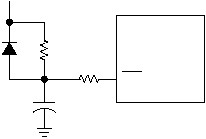
Figure 2-11 shows the recommended external reset circuit. The
external reset circuit is required only if the IOVDD rise time has the
possibility of being too slow.
Figure 2-11 External Reset Circuit
The diode D discharges the capacitor when IOVDD is powered
down.
R1 = 100
W
to 1K
W
will limit any current flowing into RST from
external capacitor C1. This protects the RST pin from breakdown
due to Electrostatic Discharge (ESD) or Electrical Overstress
(EOS).
R2 < 40K
W
is recommended to make sure that voltage drop
across R2 leaves the RST pin above a Vih level.
C1 should be chosen so that R2 × C1 exceeds the time period
required for IOVDD to reach a valid operating voltage.
IOVDD
C1
R2
R1
515-021.eps
RST
IP2022
