IP2022 User’s Manual—System Architecture
www.ubicom.com
49
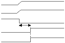
Figure 2-9 shows the on-chip Power-On Reset sequence in which
the RST and IOVDD pins are tied together. The IOVDD signal is
stable before the startup timer expires. In this case, the CPU
receives a reliable reset.
Figure 2-9 Power-On Reset, RST Tied to IOVDD
IOVDD
RST
POR
Tstartup
Startup Timer
(Time-Out)
Internal
Rest Signal
515-022.eps
