System Architecture—IP2022 User’s Manual
48
www.ubicom.com
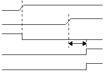
Figure 2-8 shows a power-up sequence in which RST is not tied
to the IOVDD pin and the IOVDD signal is allowed to rise and
stabilize before RST pin is brought high. The device will actually
come out of reset after the startup stabilization period (Tstartup)
from RST going high. The WUDX2:0 bits of the FUSE0 register
specify the length of the stabilization period.
Figure 2-8 Power-On Reset Timing, Separate RST Signal
The brown-out circuitry resets the chip when device power (AVdd)
dips below its minimum allowed value, but not to zero, and then
recovers to the normal value.
515-019.eps
IOVDD
RST
POR
Tstartup
Startup Timer3
(Time-Out)
Internal
Rest Signal
