In-System Debugging—IP2022 User’s Manual
354
www.ubicom.com
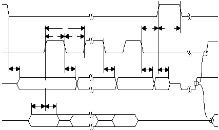
The timing parameters are shown in Figure 5-9. The timing
requirements for the ISD/ISP interface are listed in Table 5-4.
Figure 5-9 ISD/ISP Timing Diagram
TRST VOL
Output low voltage (I = 0 mA)
-0.3
0.5
TRST VOL
Output low voltage (I = 6 mA)
-0.3
0.5
TRST TL
Reset duration (low time)
90
100
110
ms
Table 5-3 ISD/ISP Electrical Specifications (continued)
Symbol
Parameter
Min
Typ
Max Units
MSB IN
BITS 22..1
LSB IN
BITS 22..1
LSB OUT
X
515-073.eps
TSS
TSCK
TSO
TSI
t1
t3
t4
t2
t7
t6
t5
t7
t7
t9
t10
t8
MSB OUT
Wait for
DONE Bit
