IP2022 User’s Manual—In-System Debugging
www.ubicom.com
345
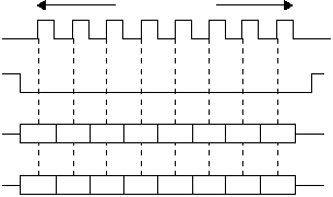
Figure 5-4 SPI Bus Timing Diagram
The ISD/ISP interface could be driven by an SPI bus master that
sends three bytes for each command. The SPI slave select signal
TSS must not be negated between each byte transfer, i.e. it must
stay asserted for the whole command including the operand word.
The TSS signal must be driven low before the command, stay low
between the command byte and operand word, and must be
released after the operand word. In other words, TSS falling
indicates the start of a frame, and TSS rising indicates the end of
a frame. The TSS slave select signal allows individual device
selection, which could be used for the verification stage after gang
programming multiple parts connected to the same programmer.
515-048.eps
TSCK
24 Bits Transferred
TSS
TSO
MSB
Bit-23
Bit-22
...
Bit 4
Bit 3
Bit 2
Bit 1
Bit 0
TSI
MSB
Bit-23
Bit-22
...
Bit 4
Bit 3
Bit 2
Bit 1
Bit 0
