In-System Debugging—IP2022 User’s Manual
344
www.ubicom.com
5.3.1
Data Transfer
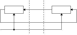
An SPI bus connection between an SPI master and an SPI slave
is like two shift registers connected in a circular configuration, as
shown in Figure 5-3. Data shifted out of the most-significant bit of
the SPI master shift register is driven on the TSI signal, which is
shifted into the least-significant bit of the SPI slave shift register.
Data shifted out of the most-significant bit of the SPI slave shift
register is driven on the TSO signal, which is shifted into the least-
significant bit of the SPI master shift register.
Figure 5-3 SPI Serial Data Transmission
Data is simultaneously transmitted and received on every transfer,
as shown in Figure 5-4. The TSCK clock signal of the SPI bus
synchronizes the shifting and sampling of the data on the two
serial data lines, both of which occur on the rising edge of TSCK.
515-047.eps
24-Bit Shift
Register
TSO
TSI
TSCK
24-Bit Shift
Register
IP2022
Debugger
/Programmer
Shift
Clock
