IP2022 User’s Manual—In-System Debugging
www.ubicom.com
335
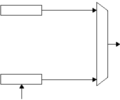
Figure 5-2 FUSE0 Register Selection
A typical sequence of commands is shown below:
1.
OPEN—Begin ISD/ISP communication.
2.
INITIALIZE—Loads and enables a temporary copy of the
FUSE0 register.
3.
DEBUG_RESET—This does not affect the clock selection
circuit; acts as BREAK command implicitly.
4.
BULK_ERASE—Erase all flash memory bits, optionally in-
cluding the configuration block.
5.
ADDR_HI—Load high word of address pointer.
6.
ADDR_LO—Load low word of address pointer.
FUSE0 Register
515-051.eps
FUSE0 Register
Loaded From Flash
Configuration Block
During Hardware Reset
Clock Source Select,
PLL Bypass,
Flash Timing, etc.
Enabled by
INITIALIZE
Command
Enabled by
RESET_ALL
Command or
Hardware Reset
Temporary Register
Loaded From INITIALIZE
Command Operand Word
