IP2022 User’s Manual—Peripherals
www.ubicom.com
269
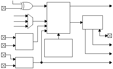
Figure 4-7 Clock/Data Separation and EOP Detection
The SxRXP and SxRXM pins should not both be grounded or left
floating, otherwise a false EOP condition may be detected. For
those interfaces which sense an EOP condition (i.e. any mode
except UART), at least one of these inputs should be driven high
to prevent spurious EOP events.
The synchronization pattern register (SxRSYNC) is used for USB
and 10Base-T protocols for detecting bit patterns that signal the
start of a frame. For USB, this register is loaded with 00000001,
while for 10Base-T, it is 10101011 (also called the SFD, start of
frame delimiter). The incoming data stream, after passing through
515-003.eps
Clock/Data
Separation
and
Start
Condition
Detection
Receive Polarity
Reversal Bit
SxCLK
Receive
Clock
Receive
Data
Transmit
Clock
Clock
Data
EOP
UART Clock
Divider
EOP
Detection
Synchronization
Pattern
Register
(SxRSYNC)
SxRXP
Input
SxRXD
Input
Serial PLL Clock
OSC Clock
RTCLK
SxRXM
Input
Ethernet
Squelch
Circuit
SxRx+
SxRx-
