Peripherals—IP2022 User’s Manual
246
www.ubicom.com
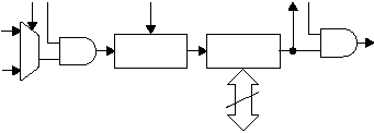
Figure 4-4 shows the Real-Time Timer logic.
Figure 4-4 Real-Time Timer Block Diagram
The real-time timer is readable and writable as the RTTMR
register. The control and status register for the real-time timer is
the RTCFG register, as described in Section 4.3.1.
The RTEOS bit in the XCFG register selects the sampling mode
for the external input. If the RTEOS bit is set, the external input is
over-sampled with the system clock. The CPU can always read
the value in the RTTMR register, however, the system clock must
be at least twice the frequency of the external input. If the system
clock source is changed to RTCLK or turned off, then the RTEOS
bit must be clear for the Real-Time Timer to function.
If the RTEOS bit is clear then the external input directly clocks the
Real-Time Timer (i.e. RTCLK is not oversampled). The Real-Time
Timer will always function whether the clock input is synchronous
or asynchronous. However, the CPU cannot reliably read the
515-015.eps
RTTMR
Register
RTIE
RTIF
Real-Time
Timer Interrupt
15-Bit
Prescaler
OSC
Clock
RTCLK
RTEN
RTPS 3:0
RTSS
Data Bus
8
