Peripherals—IP2022 User’s Manual
236
www.ubicom.com
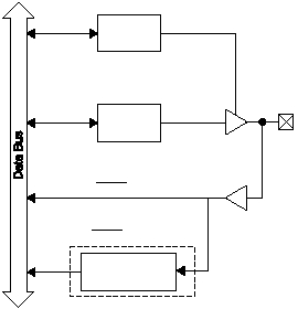
Figure 4-1 shows the internal hardware structure and
configuration registers for each pin of a port.
Figure 4-1 Port Pin Block Diagram
4.1.1
Port B Interrupts
Any of the 8 Port B pins can be configured as an external interrupt
input. Logic on these inputs can be programmed to sense rising or
falling edges. When an edge is detected, the interrupt flag for the
port pin is set.
The recommended initialization sequence is:
515-030.eps
Port Pin
RxDIR
Register
RxIN Register
(SYNC bit set)
0 = Output
1 = Hi-Z Input
RxOUT
Register
Synchronization
Register
RxIN Register
(SYNC bit clear)
