© 2001 Ubicom, Inc. All rights reserved.
- 1 -
www.ubicom.com
Ubicom™ and the Ubicom logo are trademarks of Ubicom, Inc.
All other trademarks mentioned in this document are property of their respec-
tive componies.
Application Note 38
June 2001
Universal Asynchronous
Transmitter/Receiver (UART)
Virtual Peripheral
1.0 Introduction
The UART Virtual Peripheral™ uses the SX communica-
tions controller to provide asynchronous serial communi-
cation through an RS-232 interface. The Virtual
Peripheral provides direct communication with any
device that has an RS-232 interface, such as a PC. The
Virtual Peripheral has been developed using the SX
Evaluation Board and has been tested using the SX-Key
interface from Parallax Inc. and the SXIDE integrated
development environment from Advanced Transdata Inc.
Unlike other MCUs that add functions in the form of addi-
tional silicon, the SX Series uses its fast execution rate to
emulate peripheral functions in software modules, called
Virtual Peripherals. On-chip hardware peripherals are
only provided for functions that cannot be performed effi-
ciently in software, such as timers and analog compara-
tors.
2.0 Program Description
The UART Virtual Peripheral is designed to operate at at
a fixed frequency driven by periodic interrupts. In the SX,
the mechanism used to generate periodic interrupts of a
fixed frequency is the RTCC timer. The UART virtual
peripheral can be run as one of several threads in a mul-
tithreaded interrupt service routine (ISR) or as part of a
single thread. The code this document describes con-
tains a multi-tasking ISR. Whenever an RTCC interrupt
occurs, an interrupt service routine (ISR) is called which
contains a multitasker for allocating CPU bandwidth
among any Virtual Peripherals which require interrupt
service. Each task is called a thread . The UART Virtual
Peripheral is split into a transmit section and a receive
section, and each of these sections is assigned to
isrThread1 . In this example, the multitasker implements
16 slots for calling threads, and four of these slots are
occupied by calls to
isrThread1 . Because the UART Vir-
tual Peripheral only receives service on every fourth
interrupt, most of the CPU bandwidth is available for use
by other Virtual Peripherals.
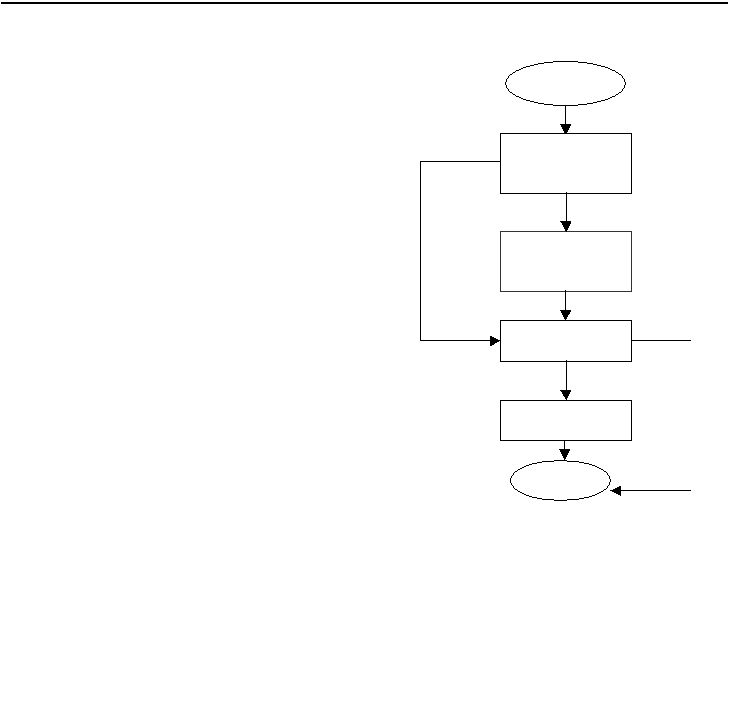
2.1
Interrupt Service Routine Flowchart
Figure2-1. Interrupt Service Routine Flowchart
START
Decrement Txdivide
value and check if it
is 0
Transmit 1 Data bit
Decrement TX
count
Check for any bit
to be received
Receive bit
END
NO
YES
NO
YES
