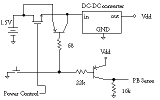
Push to start (SPST), uP keeps alive then shuts down, AND can monitor switch
Ken Webster submitted this circuit
 The PNP transistors
may be 2N3906 or similar.
The [sense input] will be at Vdd when the pushbutton is pressed (and the
circuit is powered, of course) and will be at GND otherwise.
The [power control output] is raised to Vdd to hold the power on and dropped
to GND to shut the circuit down (MOSFET must be a logic-level enhancement
mode device)
Note that PNP #1 will have its base-emitter junction reverse-biased by (Vdd
- VBE[Q2] - Vbattery+) when the circuit is powered and the pushbutton is
released. This is ok since most transistors have a BVEBO of 6 to 8 volts.
Erik Reikes of Xsilogy, Inc. says:
If you went [with a dual pole switch], I don't think you'd need all the
transistors and stuff. Just have 5V routed to the other pole (actually it
would have to be dual pole, dual throw... do they make pushbuttons like that?)
wired so that when it is released it closes a circuit to a PIC input pin.
This way you use only 1 DPDT pushbutton, one FET, and two PIC IO pins. One
IO to drive the FET and one to sense the fact that the button has been released.
Or, better yet I just thought if you use DPST you could have a pull up on
the 'button down' side when it is released you lose a voltage to the PIC.
Yes, that's better. You wire 5 volts to the other pole of the switch, and
the closed circuit supplies voltage to a PIC input pin with a pull down.
When it is released voila 0 volts (or the other way, use ground and a pull
up at the PIC, whichever seems best.).
 The PNP transistors
may be 2N3906 or similar.