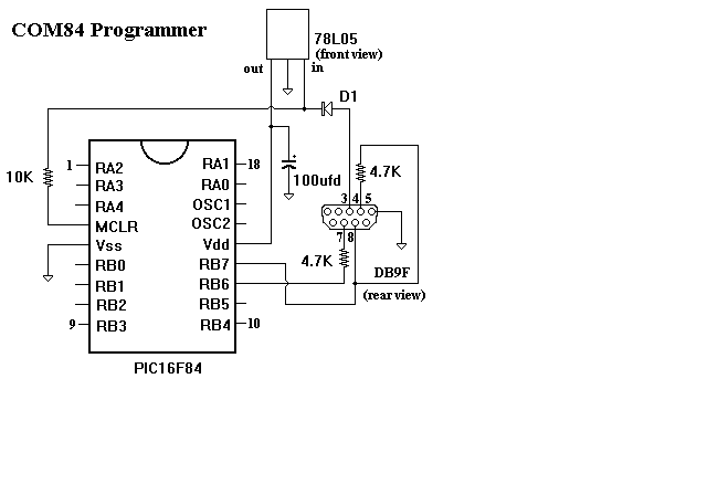
COM84 is a serial port programmer which uses very few components.

I found this amazing little programer at:
http://websites.ntl.com/~matthew.rowe/micros/prog.htm This is not my
design. I just found that it works for me and is cheap and very convenient.
I thought it might help others if I shared the construction details.
Parts used for the programmer:
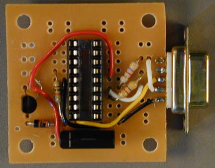
Here is a top view of the board:

The black rectangle at the bottom is the electrolytic capacitor, (+ end to the left). I was able to bend the leads out and down to holes in the pads. Round caps may be more difficult to position. You may want to consider drilling holes and running leads to the pads on the bottom side of the board.
The diode is to the left of the cap, cathode marking to the outside of the board. It is connected to a pad also holding the input to the 5 volt regulator.
Above the diode, the black, almost circular part is the regulator. If you face the flat part of the regulator the three pins, left to right are: output, ground and input. Notice the short jumper wire from the middle lead of the regulator to the rightmost of the set of holes above the regulator.
The 18 pin socket faces upward and is as high as it can go, leaving the bottom pads free for other components. The rightmost of these turns out to be ground and has black wires to it. This orientation of the PIC socket was choosen so that when the PIC is inserted with the DB9F pointing away from you, the writing on the PIC is in the normal reading position. This helps warn you from inserting it backwards.
The pins on the DB9F socket run 1 - 5 top to bottom. Only 3 of these have wires attached:
Also notice the white jumper from PIC pin 13, (RB7), going to to pad on DB9F pin 8, (CTS).
A 4.7K resistor on PIC pin 12, (RB6), connects to DB9F pin 7, (RTS).
PIC pin 14, (Vdd) connects by red wires to the output of the 5 volt regulator and + terminal of the capacitor.
Here is a bottom view of the board:
DB9F pins are 9 - 6 top to bottom, 9 and 6 are open and shouldn't touch any pads, 7 and 8 have wires inserted, soldered to pads. Other than the board being jammed between the pins, this is the main support for the board. A little epoxy between the DB9F and board, (outside the pins), wouldn't hurt.
There are three areas where the traces have been cut and scrapped away between 3 hole pin pads and the pads on the outer edges. Five have been scrapped away on the right and three at the upper left. Also, on the upper center left, part of a backwards 'L' shaped pad has been scrapped away to create two pads, one for the capacitor + lead and the other for the 10K resistor, yellow wire and diode anode. All unused PIC pins should be soldered to their pads to make the socket stable.
The programmer could be plugged directly in a COM port on the computer but might be hard to reach. I use an Atari joystick extension cable to be able to plug and unplug the programmer at a convenient location. Just make sure all the appropriate wires connect through in the cable.
I also find it useful to first place the PIC in a machine pin, 18 pin DIP socket which is then placed in the programmer socket. Keeping the PIC in the machine pin socket protects from bending the PIC pins. After a few bends they tend to break off. I usually insert a screwdriver blade between the machine pin and programmer socket to separate them, ( unplug the programmer first).
The programming software I use is called PIX. The latest version, 1.13 PIX
can be found at:
http://home5.swipnet.se/~w-53783
download the file pix113b.zip
A file called PIX.CFG has to be edited to work with this programmer. Put
in or remove semicolons to decide which options are active. Choose
'Port=Com4',(change to the COM port # you use). Use 'Programmer=Ludi' for
the programmer. I couldn't find much in the way of directions on how to use
the programmer, but it seems pretty straight forward. Load the file using
F3, (sometimes the command line seems to work also). Burn the program into
the PIC with F9.
Questions:
hello,
I'm trying to program something on a pic16f84a, I've build your com84 programmer. with mplab I create a hex file, that hex file I then load in the pic.exe program. but when I burn the controller I get the following message " blow programm error at 0000h pic = 1000 2826 wanted". Note that I use Ludi on Com1.
Can somebody please help me?
thnx
Hi,
I have a couple of questions:
1. Can I use IC-Prog with this programmer?
2. Is this programmer compatible with the Ludipipo programmer?
Thanks in advance,
David E.
edavid@1net.gr
i vae a problem, I'm trying to make this conntroller, but when I use the 5rd(gnd) and the 3rd(TD) pin, the gnd emits +10v and the RTD emits -10v so i don't know which to adopt as gnd because of the capacitors
I can't download PIX from the website mentioned above. Could you give me another link? Have anybody try to program F84A with COM84?Does it work?Or we must modify the circuit? I've tried to program F84A with PICPRO but it didn't work. Thanks to you all.
www.piclist.com/techref/piclist/cheapic/COM84.htm hi, from the com84 website programmer circuit, any slight modification can be made to used for PIC16F84A? i think the only different is the programming flash current between PIC16F84 and PIC16F84A. I'm using MPLAB to output my hex file and plan to use PIX programming software. this should be no problem right? i'm using MPASM because it allows simulation. thanks in advance
Comments:
A newer version of the PIX software is available, version 113b. You can find it at http://ftp.iasi.roedu.net/mirrors/ftp.tapr.org/picsig/software/pix113b.zip Also, the PIC16F84 is pin for pin compatable with the PIC16F84A so you won't need to change the programmer for use with that chip. Purchasing the components required for this programmer in the UK is available via Maplin Electronics
See also: