My major aim was to design a hardware/SW to implement a generic printer device. I planed to use inkjet head as an actuator. Later the same structure can be used to control laser/edm head also. I used my previous experiences on Epson CX4200/4800 because of that my knowledge is limited to drive Epson piezo heads but their head is much more complicated than Xaar or Spectra heads.
As a general rule piezo heads can be used to eject different type of liquids but for Epson head never try to use anything that is solvent based. The main reason is inside the head most parts are glued together and it is very easy to damage it.
In my implementation, I try to use minimum computational power for the micro and try to do all the timing related tasks on the fpga and keep all bulk storage at the PC side.
As a summary:
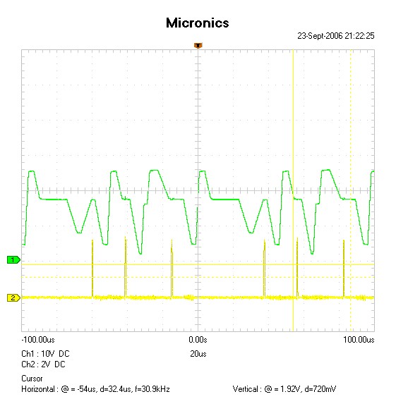
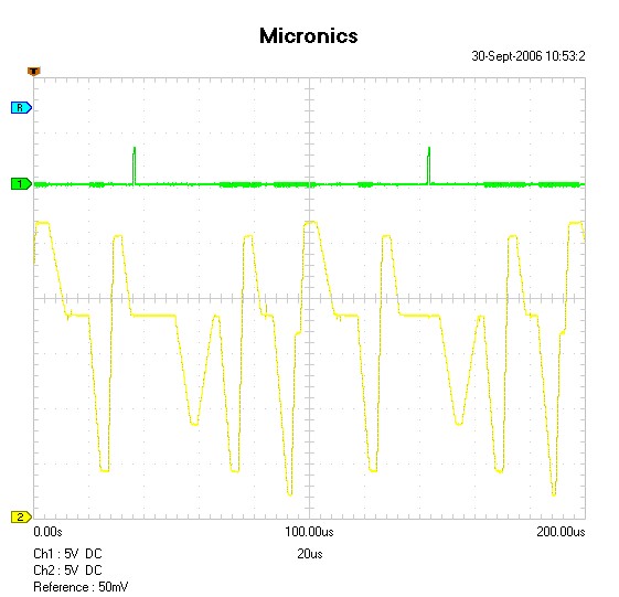
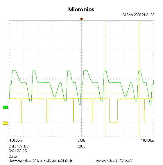
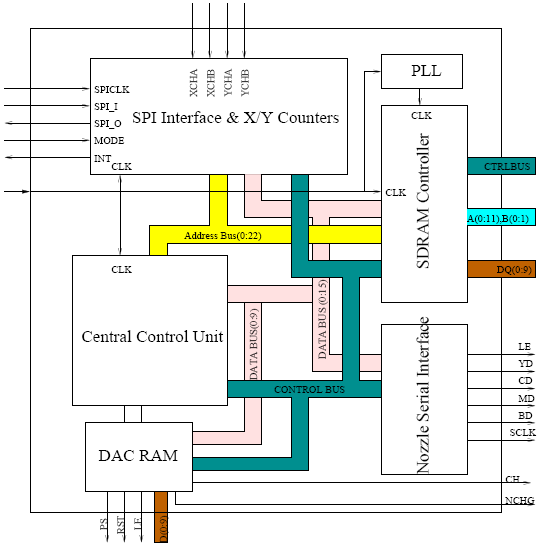
I uploaded schematics, a figure showing implemented blocks inside fpga and Epson head driving signals
All colors data are sampled (latched) with CLK signal. In Epson head each dot is represented by 2 bits therefore if each color has a 90 nozzles it means that we need to send 180 bits, in addition to that it also requires a waveform select bits in my case it was 32 bits. So it requires 212 bits data transfer for per 90 nozzles.
Common and CH signals

Common and LATCH (LE) signals

Common and NCHG signals

2 bits are used to select a different drop size for each dot. For example:
The waveform select bits (32 in my case) is used to assign physical waveform number to 2 bits representation, so in this case we have 32 bits and maximum 4 possibility for each dot, we can select 1 out of 8(=32/4) possible waveforms for each dot. This is common for all 90 nozzles.
On X-axis I have 720 dpi linear encoder(quadrature decoding) and if assume head travels 8" in 2 seconds we have ~350 microseconds between each encoder pulse. During this time we need to download next encoder position data so our head clock period should be 3.3 microseconds maximum in the case of double edge clocking. If we double the resolution we need 1.65microseconds as a clock period.
You can find detailed information on Epson head format in US patent 6758544 B2.
Block Diagram

Source files for the FPGA can not be released due to software patent issues. Part of the code used is closed source, and can not be shared. Without that part, the rest is not useful. If you would like to participate in producing open source code, please contact the yahoo group for inkjet PCB printing...
Comments:
Volkan Sahin,
We like to stay more from you. Now we are try to control the inkjet head directly from Epson R210/R230 which has 6 colors. Please contact me by email goshacity@yahoo.com I need to learn from you.
Hello Volkan:
I like to understand why you talk about 32 bits selection wave form.I understand we only need 16 bits to select the wave we wish to fire the piezoelectric.
Another thing i like to learn is how work U103 to generate the com wave signal.
I'm trying to use a 8rows 180 nozzles per row head to create a DTG printer.
Please contact me at mollet2@cantv.net
Questions:
Hello, I'm looking to nicking a print head out of an epson printer for some project. Are there any updates on this or new resources to use? Many Thanks, Thomas.
Do you know anything about the performance of the E09A54RA DAC you used? I am debating whether to use the no spec Epson part like you did or roll my own DAC + amplifier setup. My amplifier design ended up being physically large, expensive, and has 15Mhz analog bandwidth with sort of high output impedance at .2 ohms. I just don't know how this compares to the epson part.
John L Wright of Computer Repair Says:
Volkan Sahin Could you send me an email address so that we may email each other.
I have an application for a GPL coded printer that uses Spectra heads
Thanks John Wright
Interested: