1
2
3
4
5
6
7
8
9
10
11
12
NexFlash Technologies, Inc.
11
PRELIMINARY
NXSF011C-0599
05/25/99 ©
NX26F080A
NX26F160
AC ELECTRICAL CHARACTERISTICS
5V (16 MHz)
3V (8 MHz)
Symbol
Description
Min
Typ
Max
Min
Typ Max
Unit
t
CP
SCK Serial Clock Period
62
--
--
125
--
--
ns
t
CL
, t
CH
SCK Serial Clock High or Low Time
26
--
--
57
--
--
ns
t
CR
SCK Serial Clock Rise Time
(1)
--
--
7
--
--
5
ns
t
CF
SCK Serial Clock Fall Time
(1)
--
--
7
--
--
5
ns
t
DS
SIO Setup Time to SCK Rising Edge
40
--
--
100
--
--
ns
t
DH
SIO Hold Time From SCK Rising Edge
0
--
--
0
--
--
ns
t
DV
SIO Valid after SCK
(2)
--
--
60
--
--
115
ns
t
RESET
SCK Low Duration for
1.5
--
5
3
--
10
µ
s
Valid Reset or Standby
(See Figures 9 & 10)
t
RP
Read Pre-data Delay
(See Figure 9)
30
--
--
100
--
--
µ
s
t
WP
Erase/Write Program Time
(3)
NX26F080A
--
3
5
--
5
10
ms
(See Figure 10)
NX26F160
--
4
5.5
--
25
32
Notes:
1. Test points are 10% and 90% points for rise/fall times. All other timings are measured at the 50% point.
2. With 50 pF (8 MHz) or 30 pF (16 MHz) load SIO to GND.
3. The NX26F080A and NX26F160 are designed for Erase/Write endurances of 10K cycles. Endurance in the range of 100K
cycles can be obtained using ECC software methods like those provided in the SFK Serial Flash Development Kit.
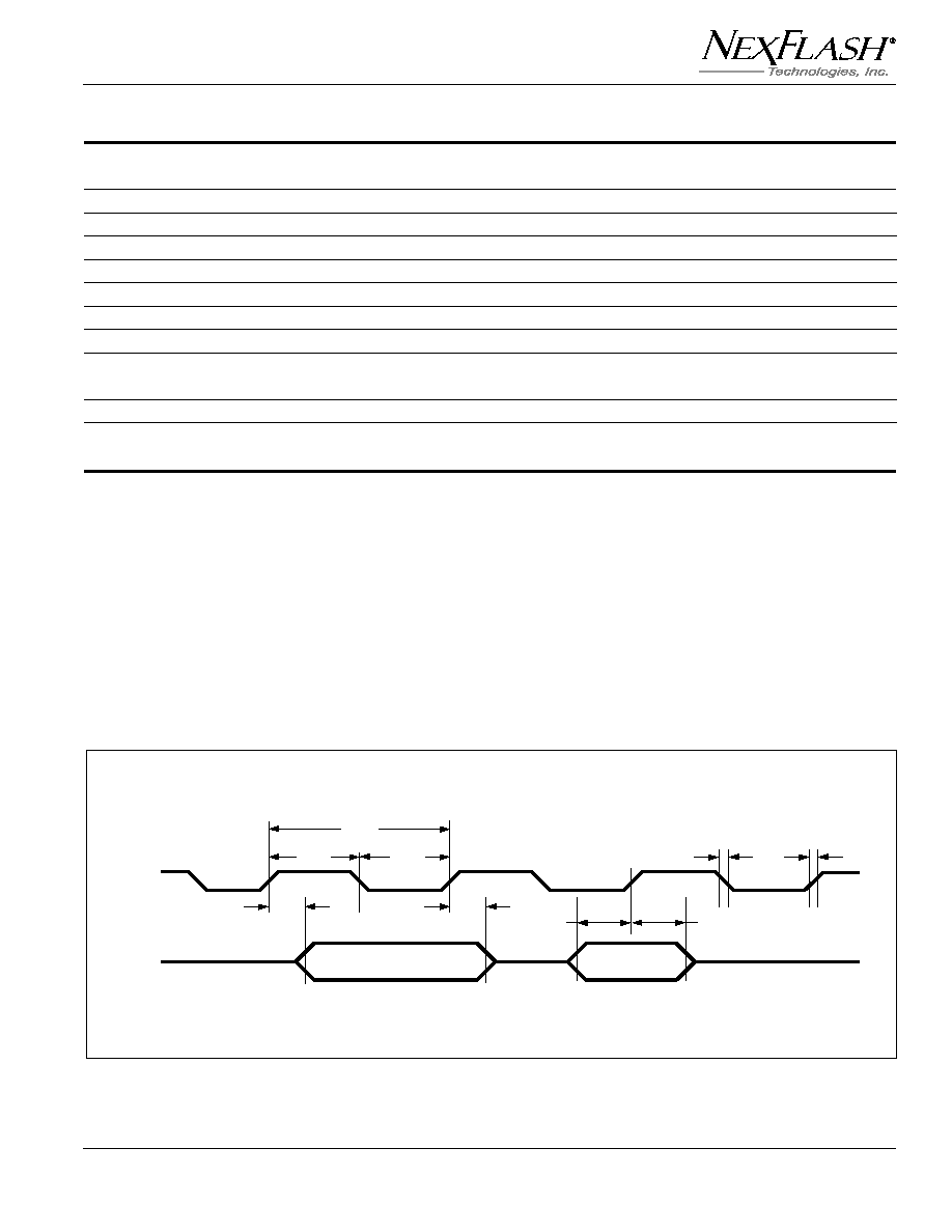
SCK
SIO
Read
Write
t
CP
t
CH
t
CL
t
DS
t
DH
t
CF
t
CR
t
DV
t
DV
CLOCK AND DATA TIMING
