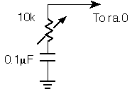
measures a variable resistance.
PBASIC's Pot command allows you to measure resistance without an external analog-to-digital converter. All that's required is a capacitor to set up a timing circuit as shown below.

Pot works by fully charging the capacitor, then measuring the time required to discharge it through the series resistance. This time is proportional to the resistance of the pot. The listing shows the technique. The Pot I/O pin is set up as an output. Then the capacitor is fully charged by making the Pot pin high for a period equal to 5 x R x C, where R is the maximum resistance of the pot, and C is the value of the capacitor. In this case, that is 5 x (10 x 103) x (0.1 x 10-6) = 5 x 10⁻³ seconds or 5 milliseconds.
Once the capacitor is fully charged, the program discharges it a little at a time, periodically changing the pin to input to determine whether it's low yet. If not, Pot increments a counter and tries again until the pin goes low.
You can adapt this technique to practically any combination of R and C. However, if C is greater than 0.1µF, it's a good idea to add a fixed series resistor of 220 ohms or so between the I/O pin and the pot itself. This limits the maximum current through the I/O pin in the event that the pot resistance is near 0 and the capacitor is initially discharged.
The PBASIC Pot routine includes a scale factor that can be used to calibrate a particular combination of R and C to produce full-range results (0 to 255). That feature undoubtedly draws on built-in math routines. You may not need scaling capabilities, so the demonstration here scales the Pot results by shifting them right. This is equivalent to integer division by two. It doesn't provide exactly full-scale results, but it keeps the routine compact.
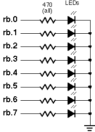
To see Pot in operation, connect the circuits above and below to an erasable PIC or PIC emulator, such as the Parallax downloader. Assemble and run POT.SRC. When you adjust the pot, the binary value displayed on the LEDs will change.

;
; ***************************************************************************
; ***  Bubble Software Parallax to PIC Source Converter. Copyright 1999.  ***
; ***  http://www.bubblesoftonline.com                 email: sales@picnpoke.com  ***
; ***************************************************************************
;
; POT
; This program shows a technique for reading resistance. The pot input pin can
; only be changed during assembly, not once the program is running.

	P = pic16c55
	#include <16c55.inc>   ; processor assembler definitions
	_CONFIG _xt_osc & _wdt_off & _protect_off
 reset start

 org 8
temp Res d'1' 	; Temporary counter for delay.
potL Res d'1' 	; Low byte of Pot measurement.
potH Res d'1' 	; High byte of Pot measurement.
pot equ		;ra.0 Pin assigned to pot.
out_pot equd'0'	; Value to set ra.0 to output for pot.
in_pot equd'1'	; Value to set ra.0 to input for pot.

 org 0
start        MOVLW out_pot              ; RA.0 to output.
             TRIS 5h
             MOVLW d'0'                 ; All outputs for LEDs.
             TRIS 6h
             BSF 5h,d'0'                ; Start charging cap.
             MOVLW d'8'                 ; Set up for 6-ms delay: 8 trips
             MOVWF potL
start_wait   DECFSZ temp                ; through outside loop x 256
             GOTO start_wait
             DECFSZ potL                ; x 3 cycles for inside loop = 6.1 ms.
             GOTO start_wait
             CLRF potL
             CLRF potH
             MOVLW in_pot               ; Get input from pot.
             TRIS 5h
             BCF 5h,d'0'                ; Clear output latch for pot bit.
start_loop   BTFSS 5h,d'0'              ; IF pot = 0 THEN :done
             GOTO start_done
             MOVLW out_pot              ; Discharge cap a little.
             TRIS 5h
             MOVLW in_pot               ; Change pot pin to input.
             TRIS 5h
             INCF potL                  ; Incerement potL.
             BTFSC status,z             ; If zero then potL overfolowed, so
             INCFSZ potH                ; increment potH. If it overflows, exit.
             GOTO start_loop            ; Overflowed? No: loop.
start_done   MOVLW d'2'                 ; Divide 16-bit number represented by
             MOVWF temp
start_div    BCF status,c               ; potH and potL by 2^temp (in this case,
             RRF potH                   ; 2^2 or 4). This scales the pot value to
             RRF potL                   ; fit within an 8-bit range.
             DECFSZ temp
             GOTO start_div
             MOVF potL,w                ; Show the outcome on LEDs.
             MOVWF 6h
             GOTO start                 ; Do it again


             end
; POT
; This program shows a technique for reading resistance. The pot input pin can
; only be changed during assembly, not once the program is running.

	device	pic16c55,xt_osc,wdt_off,protect_off
	reset	start

	org	8
temp	ds	1	; Temporary counter for delay.
potL	ds	1	; Low byte of Pot measurement.
potH	ds	1	; High byte of Pot measurement.
pot	=	ra.0	; Pin assigned to pot.
out_pot =	0	; Value to set ra.0 to output for pot.
in_pot	=	1	; Value to set ra.0 to input for pot.

	org	0
start	mov	!ra,#out_pot	; RA.0 to output.
	mov	!rb,#0		; All outputs for LEDs.
	setb	pot		; Start charging cap.
	mov	potL,#8 	; Set up for 6-ms delay: 8 trips
:wait	djnz	temp,:wait	; through outside loop x 256
	djnz	potL,:wait	; x 3 cycles for inside loop = 6.1 ms.
	clr	potL
	clr	potH
	mov	!ra,#in_pot	; Get input from pot.
	clrb	pot		; Clear output latch for pot bit.
:loop	jnb	pot,:done	; IF pot = 0 THEN :done
	mov	!ra,#out_pot	; Discharge cap a little.
	mov	!ra,#in_pot	; Change pot pin to input.
	inc	potL		; Incerement potL.
	snz			; If zero then potL overfolowed, so
	incsz	potH		; increment potH. If it overflows, exit.
	jmp	:loop		; Overflowed? No: loop.
:done	mov	temp,#2 	; Divide 16-bit number represented by
:div	clc			; potH and potL by 2^temp (in this case,
	rr	potH		; 2^2 or 4). This scales the pot value to
	rr	potL		; fit within an 8-bit range.
	djnz	temp,:div
	mov	rb,potL 	; Show the outcome on LEDs.
	jmp	start		; Do it again
See also:
See: