Description
This is a PIC16F870 based speed controller for electrical powered
radio controlled vehicles. The circuit is connected to a
standard R/C reciever and is placed between the battery
and the motor.
It will read the length of the pulses from
the reciever and output a pulse with modulated signal to
a MOSFET transistor that will feed the motor with current
from the batteries.
The circuit also include a break that
will short circuit the motor and forces it stop.
The PIC is programmed with the five ICSP programming
connectors on the PCB. I use a JDM PIC programmer for
programming the PIC.
Send any comments to: johanstrombom@hotmail.com
How to use:
Connect the battery to BAT+ and BAT-
Connect the motor to MOT+ and MOT-
Connect the reciever to the three reciever connectors
on the PCB
Files:
1.asm PIC Source code
1.hex assembled PIC code
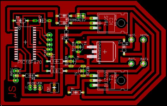
1.brd PCB Layout, EAGLE
1.pl Part list
1.jpg Picture of the PCB layout (jpg)
Part-list
Oscillator 4Mhz Ceramic resonator, 3 leads
IC1 PIC16F870
IC2 7805 +5V Regulator
R1-R4, R6 10k resistors
R5 30k resistor
R7-R9 0 ohm
T1 MTB75N05HD MOSFET Transistor
T2 BUZ10 MOSFET Transistor
T3-T5 BC338 NPN Transistors
This board is available from Olimex