by Jan Panteltje
From: http://panteltje.com/panteltje/pic/freq_pic/
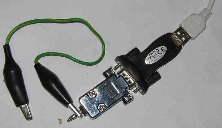
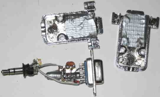 Very nice "Dead Bug" Construction!
 ;**************************************************************************
; FILE: counter.asm *
; CONTENTS: Simple low-cost digital frequency meter using a PIC 16F628 *
; AUTHOR: Wolfgang Buescher, DL4YHF *
; (based on a work by James Hutchby, MadLab, 1996) *
; REVISIONS: (latest entry first) *
; 2009-08-27 - Added RS232 output option 1200 Bd by Jan Panteltje *
; 2006-05-31 - Added the 'power-save' option which temporarily puts the *
; PIC to sleep (with only the watchdog-oscillator running) *
; 2006-05-15 - New entry in the preconfigured frequency table for 4-MHz *
; IF filters (like "Miss Mosquita" [Moskita] by DK1HE) *
; 2005-08-24 - Cured a bug in the COMMON ANODE decimal point setting . *
; (the "^0xFF" for the AND-mask was missing in macro 'conv') *
; 2005-03-21 - Added a few conditionals to use the same sourcecode *
; to drive a COMMON ANODE display ( DISPLAY_VARIANT_3 ) *
; 2004-03-14 - Fixed a range-switching bug around 8 MHz . *
; - Support TWO different display variants now, *
; optimized for different board layouts, and different clock *
; frequencies (4 MHz for variant 1, 20 MHz for variant 2). *
; 2004-03-05 - Added the feature to add or subtract a frequency offset . *
; 2004-02-18 - Migration to a PIC16F628 with 4 MHz crystal (el Cheapo) *
; - Changed the LED patterns '6' and '9' because they looked *
; like 'b' and 'q' in the old counter version . *
; - Added the auto-ranging feature *
; - Stepped from 24-bit to 32-bit integer arithmetic, to be *
; able to count 50 MHz with 1-second gate time, *
; or (at least) adjust ANY result for the ANY prescaler *
; division ratio, which may give pretty large numbers . *
; - A PIC16F628 worked up to 63 MHz with this firmware . *
;**************************************************************************
list P=16F648a
; #include <p16F628.inc> ; processor specific definitions
#include <p16f648a.inc> ; processor specific definitions
; Uncomment this if you want RS232 output
#define RS232_OUT
; Uncomment the next line if you want pin 8 of the PIC to directly drive a RS232 line (without MAX232 or such).
#define NON_INVERTING_RS232_OUT
; BAUD_DIVIDER set to 1 for 9600 Bd, 2 for 4800 Bd, 4 for 2400 Bd, 8 for 1200 Bd, 16 for 600 Bd, 32 for 300 Bd, 64 for 150 Bd, and 128 for 75 Bd.
; Note: for 9600 Bd set BIT_DELAY to 27, or basically a bit lower then for the other baudrates, due to more relative time spend in other instructions.
#define BAUD_DIVIDER d'8' ; 1200 Baud
; set baudrate, for small deviations of the internal oscillator this may need to be adapted.
#define BIT_DELAY d'165' ; approx 165 for 1200 Bd with 20 MHz clock
; for software RS232 out, NOT using UART
#define RS232_PORT PORTB
#define RS232_BIT D'2' ; RB2, pin 8
; print options, all field active looks like:
; 00000050 50 Hz 0.050 kHz
; 19999968 19,999,968 Hz 19.999 MHz
; Uncomment this if you want the first field printed.
#define RS232_PRINT_FIELD_1
; Uncomment this if you want the secind field printed.
#define RS232_PRINT_FIELD_2
; Uncomment this if you want the third field printed.
;#define RS232_PRINT_FIELD_3
; Note: The first field is for parsing by user space programs. it is recommanded to always leave the field active.
; for unit printing
#define KILOHERTZ_FLAG 1
#define NO_INPUT_FLAG 2
#define ZERO_SUPPRESSION_FLAG 4
#define DISPLAY_VARIANT_2
#define DEBUG 0 ; DEBUG=1 for simulation, DEBUG=0 for real hardware
; Selection of LED display control bits... since 2005, three different variants.
; Select ONE OF THESE in MPLAB under "Project".."Build Options".."Macro Definitions"!
; DISP_VARIANT=1 : first prototype, PIC on left side of display
; DISP_VARIANT=2 : second prototype, separated PIC and display board
; DISP_VARIANT=3 : similar as (2), but for COMMON CATHODE display
; Unfortunately it seems impossible to assign a NUMERIC VALUE to a macro
; in MPLAB (not in MPASM!) ....
#ifdef DISPLAY_VARIANT_1
#define DISP_VARIANT 1 ; very first (old) prototype by DL4YHF
#define COMMON_ANODE 0
#define COMMON_CATHODE 1
#else
#ifdef DISPLAY_VARIANT_2
#define DISP_VARIANT 2 ; 5 digits, new layout, COMMON CATHODE
#define COMMON_ANODE 0
#define COMMON_CATHODE 1
#else
#ifdef DISPLAY_VARIANT_3 ; added 2005-03-21 :
#define DISP_VARIANT 3 ; similar as (2), but for COMMON ANODE display
#define COMMON_ANODE 1
#define COMMON_CATHODE 0
#else
#define DISP_VARIANT 4
#define COMMON_ANODE 0
#define COMMON_CATHODE 1
; "Error, Must define DISPLAY_VARIANT_1, .._2, or .._3 under project options"
; With MPLAB: Project..Build Options..Project..MPASM..Macro Definitions..Add
#endif
#endif
#endif
;**************************************************************************
; *
; Summary *
; *
;**************************************************************************
; The software functions as a frequency meter with an input signal
; range of 1 Hz to ~ 50 MHz and with an accuracy of +/- 1Hz
; if the oscillator crystal is properly trimmed .
; Signal pulses are counted over a fixed time interval of 1/4 second to
; 1 second (gate time). High frequency pulses are counted over 1/4 s
; to make the meter more responsive with no loss of displayed accuracy.
; Pulses are counted using Timer 0 of the PIC,
; which is set to increment on rising edges on the TMR0 pin. The 8-bit
; hardware register is extended by software into a 32-bit pulse counter.
; If timer 0 rolls over (msb 1 -> 0) between successive polls then the
; high two bytes of the pulse counter are incremented.
; Timer 0 is unable to count more than one pulse per instruction cycle
; (per 4 clock cycles) so the prescaler is used at frequencies above
; 1MHz (4MHz clock / 4) and also to ensure that pulses are not lost
; between polls of timer 0 (which would happen if more than 128 pulses were
; received). Fortunately the prescaler is an asynchronous counter
; which works up to a few ten MHz (sometimes as far as 60 MHz) .
; Timing is based on a software loop of known execution period . The loop
; time is 50 or 20 us which gives integer counts to time 1 s and 1/4 s .
; During this timing loop, the multiplexed LED display is updated .
; The frequency in binary is converted to decimal using a powers-of-ten
; lookup table. The binary powers of ten are repeatedly subtracted from
; the frequency to determine the individual decimal digits. The decimal
; digits are stored at the 8 bytes at 'digits'. Leading zeroes are then
; suppressed and the 4 (or 5) significant digits are converted to LED data
; for the 7-segment displays using a lookup table.
; The signal frequency is displayed on four (or five) 7-segment displays.
; The displays are multiplexed which means that only one display is enabled
; at any one time. The variable 'disp_index' contains the index of the currently
; enabled display. Each display is enabled in turn at a sufficient frequency
; that no flicker is discernable. A prescaler ('disp_timer') is used
; to set the multiplexing frequency to a few hundred Hz.
; The display shows the signal frequency in KHz or MHz, according to the
; following table:
; --------------------------
; | Frequency | Display |
; --------------------------
; | < 1Hz | 0 |
; | 1Hz | 0.001[0] | Note: kHz-dot is flashing (blinking)
; | 10Hz | 0.010[0] |
; | 100Hz | 0.100[0] |
; | 1.000KHz | 1.000[0] |
; | 10.00KHz | 10.00[0] |
; | 100.0KHz | 100.0[0] |
; | 1.000MHz | 1.000[0] | Note: MHz-dot is steady (not blinking)
; | 10.00MHz | 10.00[0] |
; --------------------------
; If there is no signal at all, a single zero is displayed in the 4th(!) digit.
; Overflows are not displayed because they cannot be detected !
;**************************************************************************
; *
; PIC config definitions *
; *
;**************************************************************************
; '__CONFIG' directive is used to embed configuration data within .asm file.
; The lables following the directive are located in the respective .inc file.
; See respective data sheet for additional information on configuration word.
; Since 2006-05-28, the watchdog must be ENABLE in the config word
; because of its wakeup-from-sleep function (see 'Sleep100ms') .
; EX(16F84:) __CONFIG _CP_OFF & _WDT_ON & _PWRTE_ON & _RC_OSC
#if (DISP_VARIANT==1) ; display variant 1 : clocked with 4 MHz (low power, "XT" )
__CONFIG _CP_OFF & _WDT_ON & _PWRTE_ON & _XT_OSC & _LVP_OFF & _BODEN_OFF & _MCLRE_OFF
#else ; display variants 2+3 : clocked with 20 MHz (needs "HS" oscillator)
__CONFIG _CP_OFF & _WDT_ON & _PWRTE_ON & _HS_OSC & _LVP_OFF & _BODEN_OFF & _MCLRE_OFF
#endif
; '__IDLOCS' directive may be used to set the 4 * 4(?!?) ID Location Bits .
; These shall be placed in the HEX file at addresses 0x2000...0x2003 .
__IDLOCS H'1234'
; (definitions of "file" registers removed. They are defined in a header file!)
;**************************************************************************
; *
; Port assignments *
; *
;**************************************************************************
PORT_A_IO equ b'0000' ; port A I/O mode (all output)
PORT_B_IO equ b'00000000' ; port B I/O mode (all output)
LEDS_PORT equ PORTB ; 7-segment LEDs port
ENABLE_PORT equ PORTA ; display enable port
; Bitmasks to control the digit outputs have been moved to enable_table .
; YHF: Note that 'display #0' is the MOST SIGNIFICANT digit !
#define IOP_PROG_MODE PORTA,5 ; digital input signal, LOW enters programming mode
;**************************************************************************
; *
; Constants and timings *
; *
;**************************************************************************
; processor clock frequency in Hz (4MHz)
#if (DISP_VARIANT==1) ; display variant 1 : clocked with 4 MHz (low power consumption)
CLOCK equ .4000000
#else ; display variants 2+3 : clocked with 20 MHz (higher resolution)
CLOCK equ .20000000
#endif
; microseconds per timing loop
#if (DISP_VARIANT==1) ; display variant 1 : clocked with 4 MHz
; 20 microseconds is impossible with 4-MHz-Crystal, so use 50 us instead !
; Make sure all gate times can be divided by this interval without remainder :
; 1 second / 50 us = 20000 (ok)
; 1/4 second / 50 us = 5000 (ok)
; 1/8 second / 50 us = 2500 (ok)
TIME equ .50
#else ; display variants 2+3 : clocked with 20 MHz
; 20 microseconds is impossible with 4-MHz-Crystal, so use 50 us instead !
; Make sure all gate times can be divided by this interval without remainder :
; 1 second / 20 us = 50000 (ok)
; 1/4 second / 20 us = 12500 (ok)
; 1/8 second / 50 us = 6250 (ok)
TIME equ .20
#endif ; variant 1 or 2+3 ?
; Clock cycles per timing loop. See subroutine count_pulses .
; Usually CYCLES=200 (for 4 MHz crystal, 50 usec - loop)
; or 400 (for 20 MHz crystal, 20 usec - loop)
CYCLES equ TIME*CLOCK/.1000000
GATE_TIME_LOOPS equ CLOCK/CYCLES ; number of gate-time loops for ONE SECOND gate time
LAMPTEST_LOOPS equ CLOCK/(.2*CYCLES) ; number of loops for a 0.5 SECOND lamp test after power-on
PROGMODE_LOOPS equ CLOCK/(.10*CYCLES) ; number of delay loops for display in PROGRAMMING MODE (0.1 sec)
; Configuration of power-saving mode :
#if( DEBUG )
PSAVE_DELAY_TIME equ .10 ; number of 0.25-sec-intervals before turning off (shorter for debugging)
#else
PSAVE_DELAY_TIME equ .60 ; number of 0.25-sec-intervals before turning off (some dozen seconds)
#endif
PSAVE_FLASHUP_TIME equ .14 ; number of 0.7(!)-second-intervals between two flashes in power-saving mode
PSAVE_MAX_DIFF equ .10 ; maximum frequency difference (range-dependent, see below)
; Unit: N times "frequency-resolution", see frequency-range table .
; Example: PSAVE_MAX_DIFF=10 means 10*4Hz in Range 1 (1..3.4 MHz) .
; Menu Indices ... must match the jump table PMDisplay + PMExecute !
MI_QUIT equ 0 ; exit from menu
MI_PSAVE equ 1 ; turn "power save"-option on and off
MI_ADD equ 2 ; save frequency offset to ADD it from now on
MI_SUB equ 3 ; save frequency offset to SUBTRACT it from now on
MI_ZERO equ 4 ; set the frequency offset to ZERO and leave menu
MI_STD_IF equ 5 ; jump into the STANDARD INTERMEDIATE FREQUENCY table..
MI_INDEX_MAX equ 5 ; normal menu indices up to MI_INDEX_MAX .
MI_IF_1 equ 6 ; show the 1st standard IF
MI_IF_2 equ 7 ; show the 2nd standard IF
MI_IF_3 equ 8 ; show the 3rd standard IF
MI_IF_4 equ 9 ; show the 4th standard IF
MI_IF_5 equ 0x0A ; show the 4th standard IF
MI_IF_QT equ 0x0B ; exit standard IF menu without changing anything
MI_IF_SUBMENU_MAX equ 0x0A
;**************************************************************************
; *
; File register usage *
; *
;**************************************************************************
; RAM memory (general purpose registers, unfortunately not the same for PIC16F84 & PIC16F628)
; in PIC16F628: RAM from 0x20..0x7F (96 bytes, 0x20.. only accessable in Bank0)
; 0xA0..0xEF (another 80 bytes in Bank1)
; 0x120..0x14F (another 48 bytes in Bank2)
; 0x0F0..0x0FF, 0x170..0x17F , 0x1F0..0x1FF are mapped to 0x70..0x7F (same in all banks)
; So use 0x70..0x7F for context saving in the PIC16F628 and forget 0x0F0.. 0xNNN !
;
; Note on the 32-bit integer arithmetics as used in this code:
; - They begin with MOST SIGNIFICANT BYTE in memory, but...
; - Every byte location has its own label here, which makes debugging
; with Microchip's simulator much easier (point the mouse on the name
; of a variable to see what I mean !)
;
tens_index equ 0x27 ; index into the powers-of-ten table
divi equ 0x28 ; power of ten (32 bits)
divi_hi equ 0x28 ; same as 'divi' : HIGH byte
divi_mh equ 0x29 ; MEDIUM HIGH byte
divi_ml equ 0x2A ; MEDIUM LOW byte
divi_lo equ 0x2B ; LOW byte
timer0_old equ 0x2C ; previous reading from timer0 register
gatecnt_hi equ 0x2D ; 16-bit counter (msb first)
gatecnt_lo equ 0x2E ; 16-bit counter (lsb last)
bTemp equ 0x2F ; temporary 8-bit register,
; may be overwritten in ALL subroutines
freq equ 0x30 ; frequency in binary (32 bits)....
freq_hi equ 0x30 ; same location, begins with HIGH byte
freq_mh equ 0x31 ; ... medium high byte
freq_ml equ 0x32 ; ... medium low byte
freq_lo equ 0x33 ; ... low byte
freq2 equ 0x34 ; frequency too, copied for programming mode
freq2_hi equ 0x34 ; same location, begins with HIGH byte
freq2_mh equ 0x35 ; ... medium high byte
freq2_ml equ 0x36 ; ... medium low byte
freq2_lo equ 0x37 ; ... low byte
foffs equ 0x38 ; frequency too, copied for programming mode
foffs_hi equ 0x38 ; same location, begins with HIGH byte
foffs_mh equ 0x39 ; ... medium high byte
foffs_ml equ 0x3A ; ... medium low byte
foffs_lo equ 0x3B ; ... low byte
menu_index equ 0x3C ; menu item for programming mode
menu_timer equ 0x3D ; used to detect how long a key was pressed
digits equ 0x40 ; frequency as decimal digits (8 bytes)...
digit_0 equ 0x40 ; same location as MOST SIGNIFICANT digit, 10-MHz
digit_1 equ 0x41 ; usually the 1-MHz-digit
digit_2 equ 0x42 ; usually the 100-kHz-digit
digit_3 equ 0x43 ; usually the 10-kHz-digit
digit_4 equ 0x44 ; usually the 1-kHz-digit
digit_5 equ 0x45 ; usually the 100-Hz-digit
digit_6 equ 0x46 ; usually the 10-Hz-digit
digit_7 equ 0x47 ; usually the 1-Hz-digit
digit_8 equ 0x48 ; must contain a blank character (or trailing zero)
display0 equ 0x49 ; display #0 data
display1 equ 0x4A ; display #1 data
display2 equ 0x4B ; display #2 data
display3 equ 0x4C ; display #3 data
display4 equ 0x4D ; display #4 data
disp_index equ 0x4E ; index of the enabled display (0 to 4 for 5-digit display)
disp_timer equ 0x4F ; display multiplex timer (5 bits)
adjust_shifts equ 0x50 ; count of 'left shifts' to compensate prescaler+gate time
blinker equ 0x51 ; prescaler for the flashing 1-kHz-dot
psave_timer equ 0x52 ; timer for power-save mode (incremented every 0.25 seconds)
psave_freq_lo equ 0x53 ; low-byte of frequency to detect changes for power-save mode
psave_flags equ 0x54 ; power-saving flags with the following bits:
#define PSFLAG_ACTIVE psave_flags,0 ; clear:normal mode, set:power-saving in action (display blanked)
options equ 0x55 ; display options with the following flag-bits:
#define OPT_PWRSAVE options,0 ; clear:normal mode, set:power-saving mode enabled
tx_reg equ 0x56
bit_count equ 0x57
baud_divider equ 0x58
delay_counter equ 0x59
print_flags equ 0x5A
temp equ 0x5B
;**************************************************************************
; *
; Macros (1) *
; *
;**************************************************************************
eep_dw macro value ; a DOUBLEWORD split into 4 bytes in the PIC's DATA EEPROM
de (value>>.24), (value>>.16)&0xFF, (value>>8)&0xFF, value&0xFF
endm
;**************************************************************************
; *
; EEPROM memory definitions *
; *
;**************************************************************************
; for PIC16F84: 0x00..0x3F were valid EEPROM locations (64 byte)
; for PIC16F628: 0x00..0x7F are valid EEPROM locations (128 byte)
#define EEPROM_ADR_FREQ_OFFSET 0x00 ; EEPROM location for frequency offset
#define EEPROM_ADR_STD_IF_TABLE 0x04 ; EEPROM location for standard IF table (4*4 byte)
#define EEPROM_ADR_OPTIONS 0x20 ; EEPROM location for "options" (flags)
; This gives warnings with gpasm 'Warning [220] Address exceeds maximum range for this processor.'
; Initial contents of DATA EEPROM:
org (0x2100+EEPROM_ADR_FREQ_OFFSET)
eep_dw .0 ; [00..03] initial frequency offset = ZERO
org (0x2100+EEPROM_ADR_STD_IF_TABLE) ; standard IF table ...
eep_dw .455000 ; [04..07] frequently used in old AM radios
eep_dw .3999000 ; [08..0B] used in "Miss Mosquita" (DK1HE / DL QRP AG)
eep_dw .4194304 ; [0C..0F] used in other homebrew amateur radio receivers
eep_dw .4433619 ; [10..13] sometimes used in homebrew amateur radio receivers
eep_dw .10700000 ; [14..17] frequently used in old FM radios
; [18..1F] reserved for other "preprogrammed" values
org (0x2100+EEPROM_ADR_OPTIONS)
de .0 ; [20] "options" (flags), cleared by default
;**************************************************************************
; *
; More Macros *
; *
;**************************************************************************
;--------------------------------------------------------------------------
; macros to implement lookup tables - these macros hide the PIC syntax
; used and make the source code more readable
; (YHF: CAUTION - BUT THESE MACROS HIDE SOME VERY NASTY PITFALLS .
; TABLE MUST NOT CROSS PAGE BORDER DUE TO 'ADDWF PCL, f' ! )
;--------------------------------------------------------------------------
cquad macro value
retlw value>>.24 ; high byte
retlw (value>>.16)&0xFF ; middle-high byte
retlw (value>>8)&0xFF ; middle-low byte
retlw value&0xFF ; low byte
endm
table macro label ; define lookup table
label addwf PCL,f ; caution: this is 'PCL' only, cannot add to the full 'PC' in a PIC !
endm
;--------------------------------------------------------------------------
; add with carry - adds the w register and the carry flag to the file
; register reg, returns the result in <reg> with the carry flag set if overflow
;--------------------------------------------------------------------------
addcwf macro reg
local add1,add2
bnc add1 ; branch if no carry set
addwf reg , f ; add byte
incf reg , f ; add carry
skpnz
setc
goto add2
add1 addwf reg,f ; add byte
add2
endm
;--------------------------------------------------------------------------
; subtract with "no-carry" - subtracts the w register and the no-carry flag
; from the file register reg, returns the result in reg with the no carry flag
; set if underflow
;--------------------------------------------------------------------------
subncwf macro reg
local sub1,sub2
bc sub1 ; branch if carry set
subwf reg, f ; subtract byte
skpnz ; subtract no carry
clrc
decf reg , f
goto sub2
sub1 subwf reg , f ; subtract byte
sub2
endm
;--------------------------------------------------------------------------
; MACRO to perform 32-bit addition - adds the four bytes at op2 to the
; three bytes at op1 (most significant bytes first), returns the result in
; op1 with op2 unchanged and the carry flag set if overflow
;--------------------------------------------------------------------------
add32 macro op1,op2 ; op1 := op1 + op2
movfw op2+3 ; add low byte (bits 7...0)
addwf op1+3,f
movfw op2+2 ; add middle-low byte (bits 15..8)
addcwf op1+2
movfw op2+1 ; add middle-high byte (bits 23...16)
addcwf op1+1
movfw op2+0 ; add high byte (bits 31...24)
addcwf op1+0
endm
;--------------------------------------------------------------------------
; MACRO to perform 32-bit subtraction - subtracts the four bytes at op2
; from the four bytes at op1 (most significant bytes first), returns the
; result in op1 with op2 unchanged and the no carry flag set if underflow
;--------------------------------------------------------------------------
sub32 macro op1,op2 ; op1 := op1 - op2
movfw op2+3 ; subtract low byte
subwf op1+3 , f
movfw op2+2 ; subtract middle low byte
subncwf op1+2
movfw op2+1 ; subtract middle high byte
subncwf op1+1
movfw op2+0 ; subtract high byte
subncwf op1+0
endm
;--------------------------------------------------------------------------
; MACRO to negate a 32-bit value ( op := 0 - op ) .
;--------------------------------------------------------------------------
neg32 macro op ; op1 := 0 - op2
local neg_done
comf op, f ; invert all 8 bits in high byte
comf op+1, f ; invert all 8 bits in middle high byte
comf op+2, f ; invert all 8 bits in middle low byte
comf op+3, f ; invert all 8 bits in low byte
; Note at this point 0x000000 would have turned into 0xFFFFFFF .
; Must add ONE to complete the TWO's COMPLIMENT calculation ( -0 = 0 ).
; Note that "incf" affects only the Z flag but not the C flag .
incfsz op+3, f ; increment low byte (bits 7...0)
goto neg_done ; if incremented result NOT zero, we're through !
incfsz op+2, f ; increment middle low byte (bits 15...8)
goto neg_done ; if incremented result NOT zero, ...
incfsz op+1, f ; increment middle high byte (bits 23...16)
goto neg_done ; if ...
incfsz op+0, f ; increment high byte (bits 31...24)
goto neg_done ;
neg_done
endm
;**********************************************************************
ORG 0x000 ; processor reset vector
goto MainInit ; go to beginning of program
; (begin of ROM is too precious to waste for ordinary code, see below...)
;**************************************************************************
; *
; Lookup tables *
; Must be at the start of the code memory to avoid crossing pages !! *
; *
;**************************************************************************
;--------------------------------------------------------------------------
; 7-segment LED data table
;--------------------------------------------------------------------------
; Index 0..9 used for decimal numbers, all other indices defined below :
CHAR_A equ .10 ; Letters A..F = HEX digits, index 10..15
CHAR_b equ .11 ;
CHAR_c equ .12 ;
CHAR_d equ .13 ;
CHAR_E equ .14 ;
CHAR_F equ .15 ;
CHAR_G equ .16 ; Other letters used in "programming" mode
CHAR_H equ .17 ;
CHAR_i equ .18 ;
BLANK equ .19 ; blank display
TEST equ .20 ; power-on display test
CHAR_P equ .21 ; A few other letters for programming mode...
CHAR_r equ .22 ;
CHAR_o equ .23 ; "Prog"
CHAR_Q equ .24 ; "Quit"
CHAR_u equ .25 ;
CHAR_t equ .26 ;
CHAR_S equ .27 ; "Sub"
CHAR_Z equ .28 ; "ZEro"
CHAR_I equ .29 ; large "I" (left aligned!) for "IF"
CHAR_J equ .30 ;
CHAR_k equ .31 ;
CHAR_L equ .32 ;
CHAR_N equ .33 ;
CHAR_V equ .34 ;
CHAR_EQ equ .35 ; "="
#if (DISP_VARIANT==1)
DPPOINT_BIT equ 4 ; decimal point bit (same for all digits)
#define _A 0x01 ; bitmask for segment A , etc ..
#define _B 0x02
#define _C 0x20
#define _D 0x08
#define _E 0x04
#define _F 0x40
#define _G 0x80
#define _DP 0x10
#endif ; DISPLAY VARIANT #1
#if (DISP_VARIANT==2) || (DISP_VARIANT==3)
DPPOINT_BIT equ 1 ; decimal point bit (same for all digits)
#define _A 0x40 ; bitmask for segment A , etc ..
#define _B 0x80
#define _C 0x04
#define _D 0x01
#define _E 0x08
#define _F 0x10
#define _G 0x20
#define _DP 0x02
#endif ; DISPLAY VARIANT #2 + #3
BLANK_PATTERN equ b'00000000' ; blank display pattern (7-segment code)
;-----------------------------------------------------------------------------
; Table to convert a decimal digit or a special character into 7-segment-code
; Note: In DL4YHF's PIC counter, all digits have the same segment connections,
; so we do not need individual conversion tables for all segments.
;
; AAAA
; F B
; F B
; GGGG
; E C
; E C
; DDDD DP
;
;-----------------------------------------------------------------------------
Digit2SevenSeg:
addwf PCL,f ; caution: this is 'PCL' only, not 'PC'. Beware of page borders.
; A = 0, B = 1, C = 5, D = 3, E = 2, F = 6, G = 7, DP = 4
#if (COMMON_ANODE)
#define SSEG_XORMASK 0xFF ; since 2005-03-21 ... never tested by the author !
#else
#define SSEG_XORMASK 0x00 ; for COMMON CATHODE: No bitwise EXOR to the pattern
#endif
retlw (_A+_B+_C+_D+_E+_F )^SSEG_XORMASK ; ABCDEF. = '0' ( # 0 )
retlw ( _B+_C )^SSEG_XORMASK ; .BC.... = '1' ( # 1 )
retlw (_A+_B +_D+_E +_G)^SSEG_XORMASK ; AB.DE.G = '2' ( # 2 )
retlw (_A+_B+_C+_D +_G)^SSEG_XORMASK ; ABCD..G = '3' ( # 3 )
retlw ( _B+_C +_F+_G)^SSEG_XORMASK ; .BC..FG = '4' ( # 4 )
retlw (_A +_C+_D +_F+_G)^SSEG_XORMASK ; A.CD.FG = '5' ( # 5 )
retlw (_A +_C+_D+_E+_F+_G)^SSEG_XORMASK ; A.CDEFG = '6' ( # 6 )
retlw (_A+_B+_C )^SSEG_XORMASK ; ABC.... = '7' ( # 7 )
retlw (_A+_B+_C+_D+_E+_F+_G)^SSEG_XORMASK ; ABCDEFG = '8' ( # 8 )
retlw (_A+_B+_C+_D +_F+_G)^SSEG_XORMASK ; ABCD.FG = '9' ( # 9 )
retlw (_A+_B+_C +_E+_F+_G)^SSEG_XORMASK ; ABC.EFG = 'A' ( # 10 )
retlw ( _C+_D+_E+_F+_G)^SSEG_XORMASK ; ..CDEFG = 'b' ( # 11 )
retlw ( _D+_E +_G)^SSEG_XORMASK ; ...DE.G = 'c' ( # 12 )
retlw ( _B+_C+_D+_E +_G)^SSEG_XORMASK ; .BCDE.G = 'd' ( # 13 )
retlw (_A +_D+_E+_F+_G)^SSEG_XORMASK ; A..DEFG = 'E' ( # 14 )
retlw (_A +_E+_F+_G)^SSEG_XORMASK ; A...EFG = 'F' ( # 15 )
retlw (_A +_C+_D+_E+_F )^SSEG_XORMASK ; A.CDEF. = 'G' ( # 16 )
retlw ( _B+_C +_E+_F+_G)^SSEG_XORMASK ; .BC.EFG = 'H' ( # 17 )
retlw ( _E )^SSEG_XORMASK ; ....E.. = 'i' ( # 18 )
retlw (BLANK_PATTERN )^SSEG_XORMASK ; ....... = ' ' ( # 19 )
retlw (b'11111111' )^SSEG_XORMASK ; all segments on ( # 20 )
; A few more letters for programming mode :
retlw (_A+_B +_E+_F+_G)^SSEG_XORMASK ; AB..EFG = 'P' ( # 21 )
retlw ( _E +_G)^SSEG_XORMASK ; ....E.G = 'r' ( # 22 )
retlw ( _C+_D+_E +_G)^SSEG_XORMASK ; ..CDE.G = 'o' ( # 23 )
retlw (_A+_B+_C +_F+_G)^SSEG_XORMASK ; ABC..FG = 'Q' ( # 24 )
retlw ( _C+_D+_E )^SSEG_XORMASK ; ..CDE.. = 'u' ( # 25 )
retlw ( _D+_E+_F+_G)^SSEG_XORMASK ; ...DEFG = 't' ( # 26 )
retlw (_A +_C+_D +_F+_G)^SSEG_XORMASK ; A.CD.FG = 'S' ( # 27 )
retlw (_A+_B +_D+_E +_G)^SSEG_XORMASK ; AB.DE.G = 'Z' ( # 28 )
retlw ( _E+_F )^SSEG_XORMASK ; ....EF. = 'I' ( # 29 )
retlw ( _B+_C+_D )^SSEG_XORMASK ; .BCD.. = 'J' ( # 30 )
retlw ( _D+_E+_F+_G)^SSEG_XORMASK ; ...DEFG = 'k' ( # 31 )
retlw ( _D+_E+_F )^SSEG_XORMASK ; ...DEF. = 'L' ( # 32 )
retlw (_A+_B+_C +_E+_F )^SSEG_XORMASK ; ABC.EF. = 'N' ( # 33 )
retlw ( _C+_D+_E+_F )^SSEG_XORMASK ; ..CDEF. = 'V' ( # 34 )
retlw ( _D +_G)^SSEG_XORMASK ; ...D..G = '=' ( # 35 )
;--------------------------------------------------------------------------
; Table to control which 7-segment display is enabled. Displays are usually
; COMMON CATHODE (variants 1+2) so pulled low to enable.
; For DISP_VARIANT=3 (COMMON ANODE), the digit-driving pattern is inverted.
; Input: W = 0 means the MOST SIGNIFICANT DIGIT (the leftmost one), etc.
; Result: VALUE to be written to ENABLE_PORT to activate the digit
;--------------------------------------------------------------------------
Digit2MuxValue: ;
addwf PCL,f ; caution: this is 'PCL' only, not 'PC'
; Note: If the program counter is affected, a command requires to instruction cycles (=8 osc cycles)
#if (DISP_VARIANT==1) ; muliplexer values for DISPLAY VARIANT #1 :
retlw b'11110111' ; most significant digit is on PA3 (!)
retlw b'11111110' ; next less significant dig. on PA0 (!)
retlw b'11111011' ; next less significant dig. on PA2 (!)
retlw b'11111101' ; 4th (sometimes the last) digit PA1 (!)
retlw b'11111111' ; 5th (OPTIONAL) least significant digit = NOT (PA3+PA2+PA1+PA0)
#endif ; DISPLAY VARIANT #1
#if (DISP_VARIANT==2) ; muliplexer values for DISPLAY VARIANT #2 (5 digits, COMMON CATHODE) :
retlw b'11110111' ; most significant digit is on PA3 (!)
retlw b'11111011' ; next less significant dig. on PA2 (!!)
retlw b'11111110' ; next less significant dig. on PA0 (!!)
retlw b'11111101' ; 4th (sometimes the last) digit PA1 (!)
retlw b'11111111' ; 5th (OPTIONAL) least significant digit = NOT (PA3+PA2+PA1+PA0)
#endif ; DISPLAY VARIANT #2
#if (DISP_VARIANT==3) ; muliplexer values for DISPLAY VARIANT #3 (5 digits, COMMON ANODE) :
; Unused bits (b7..b4) are left HIGH as above .
retlw b'11111000' ; most significant digit is on PA3 (!)
retlw b'11110100' ; next less significant dig. on PA2 (!!)
retlw b'11110001' ; next less significant dig. on PA0 (!!)
retlw b'11110010' ; 4th (sometimes the last) digit PA1 (!)
retlw b'11110000' ; 5th (OPTIONAL) least significant digit = NOT (PA3+PA2+PA1+PA0)
#endif ; DISPLAY VARIANT #2
;--------------------------------------------------------------------------
; Powers-of-ten table (32 bits, most significant byte first)
; Based on an idea by James Hutchby (MadLab, 1996) .
; Modified for 32-bit arithmetic by Wolfgang Buescher (2004).
;--------------------------------------------------------------------------
TensTable addwf PCL,f
cquad .10000000 ; 10 million is sufficient for the counter itself
cquad .1000000
cquad .100000
cquad .10000
cquad .1000
cquad .100
cquad .10
cquad .1
;--------------------------------------------------------------------------
; DISPLAY jump table for programming mode .
; Loads the display-strings like "quit" etc into the display latches.
; Input parameter: menu_index (0 .. MI_INDEX_MAX)
; Output placed in display0..display3
;
;--------------------------------------------------------------------------
PMDisplay:
movfw menu_index ; load menu index into W register
addwf PCL, f ; add W to lower part of program counter (computed jump)
goto PmDisp_Quit ; show "quit" (quit programming mode)
goto PmDisp_PSave; show "PSave"(power-saving mode on/off)
goto PmDisp_Add ; show "add " (add frequency offset)
goto PmDisp_Sub ; show "sub " (subtract frequency offset)
goto PmDisp_Zero ; show "Zero" (set frequency offset to zero)
goto PmDisp_StIF ; show "StdIF" (select standard IF from table)
goto PmDisp_IF_1 ; show 1st standard IF from table
goto PmDisp_IF_2 ; show 2nd standard IF from table
goto PmDisp_IF_3 ; show 3rd standard IF from table
goto PmDisp_IF_4 ; show 4th standard IF from table
goto PmDisp_IF_5 ; show 5th standard IF from table
goto PmDisp_Quit ; show "quit" (quit STANDARD IF menu)
; Add more display strings here if needed !
;--------------------------------------------------------------------------
; EXECUTION jump table for programming mode .
; Executes the commands "quit", "psave", "add", "sub", "zero", etc.
; Input parameter: menu_index (0 .. MI_INDEX_MAX)
;--------------------------------------------------------------------------
PMExecute: ; Execute the function belonging to menu_index
movfw menu_index ; load menu index into W register
addwf PCL, f ; add W to lower part of program counter (computed jump)
goto PmExec_Quit ; quit programming mode
goto PmExec_PSave; turn power-saving mode on/off
goto PmExec_Add ; add frequency offset from now on
goto PmExec_Sub ; subtract frequency offset from now on
goto PmExec_Zero ; set frequency offset to zero
goto PmExec_StIF ; switch to "Standard IF selection mode"
goto PmExec_SelIF ; select 1st standard IF from table
goto PmExec_SelIF ; select 2nd standard IF from table
goto PmExec_SelIF ; select 3rd standard IF from table
goto PmExec_SelIF ; select 4th standard IF from table
goto PmExec_Quit ; quit STANDARD IF menu
; Add more jumps here if needed !
;**************************************************************************
; *
; Procedures *
; *
;**************************************************************************
;--------------------------------------------------------------------------
; Configure the prescaler for TIMER 0 in the PIC's OPTION register .
;--------------------------------------------------------------------------
; Description of the OPTION register, from the PIC16F628 data sheet:
; bit 7: RBPU: PORTB Pull-up Enable bit
; 1 = PORTB pull-ups are disabled
; 0 = PORTB pull-ups are enabled by individual port latch values
; bit 6: INTEDG: Interrupt Edge Select bit
; 1 = Interrupt on rising edge of RB0/INT pin
; 0 = Interrupt on falling edge of RB0/INT pin
; bit 5: T0CS: TMR0 Clock Source Select bit
; 1 = Transition on RA4/T0CKI pin
; 0 = Internal instruction cycle clock (CLKOUT)
; bit 4: T0SE: TMR0 Source Edge Select bit
; 1 = Increment on high-to-low transition on RA4/T0CKI pin
; 0 = Increment on low-to-high transition on RA4/T0CKI pin
; bit 3: PSA: Prescaler Assignment bit
; 1 = Prescaler is assigned to the WDT
; 0 = Prescaler is assigned to the Timer0 module
; bit 2-0: PS2:PS0: Prescaler Rate Select bits, here shown for TMR0 :
; 000 = 1 : 2
; ... 111 = 1 : 256
; Note: to count EVERY pulse (1 : 1) with TMR0, the prescaler
; must be assigned to the WATCHDOG TIMER (WDT) !
; Some examples (for the OPTION register, parameter in W for SetPrescaler):
PSC_DIV_BY_2 equ b'00100000' ; let prescaler divide TMR0 by two
PSC_DIV_BY_4 equ b'00100001' ; let prescaler divide TMR0 by 4
PSC_DIV_BY_8 equ b'00100010' ; let prescaler divide TMR0 by 8
PSC_DIV_BY_16 equ b'00100011' ; let prescaler divide TMR0 by 16
PSC_DIV_BY_32 equ b'00100100' ; let prescaler divide TMR0 by 32
PSC_DIV_BY_64 equ b'00100101' ; let prescaler divide TMR0 by 64
PSC_DIV_BY_128 equ b'00100110' ; let prescaler divide TMR0 by 128
PSC_DIV_BY_256 equ b'00100111' ; let prescaler divide TMR0 by 256
SetPrescaler: ; copy W into OPTION register, avoid watchdog trouble
clrwdt ; recommended by Microchip ("switching prescaler assignment")
errorlevel -302 ; Turn off banking message for the next few instructions..
bsf STATUS, RP0 ;! setting RP0 enables access to OPTION reg
; option register is in bank1. i know. thanks for the warning.
movwf OPTION_REG ;! ex: "option" command (yucc)
bcf STATUS, RP0 ;! clearing RP0 for normal register access
errorlevel +302 ; Enable banking message again
retlw 0
PrescalerOff: ; turn the prescaler for TMR0 "off"
; (actually done by assigning the prescaler to the watchdog timer)
clrwdt ; clear watchdog timer
clrf TMR0 ; clear timer 0 AND PRESCALER(!)
errorlevel -302 ; Turn off banking message for the next few instructions..
bsf STATUS, RP0 ;! setting RP0 enables access to OPTION reg
; option register is in bank1. i know. thanks for the warning.
movlw b'00100111' ;! recommended by Microchip when
;! changing prescaler assignment from TMR0 to WDT
movwf OPTION_REG ;! ex: "option" command (yucc)
clrwdt ;! clear watchdog again
movlw b'00101111' ;! bit 3 set means PS assigned to WDT now
movwf OPTION_REG ;! ex: "option" command (yucc)
bcf STATUS, RP0 ;! clearing RP0 for normal register access
errorlevel +302 ; Enable banking message again
retlw 0
;--------------------------------------------------------------------------
; Power-saving subroutine: Puts the PIC to sleep for ROUGHLY 100 milliseconds .
; - crystal oscillator turned OFF during this phase
; - only the internal RC-oscillator for the watchdog keeps running
; - expiration of watchdog during sleep does NOT reset the PIC,
; only wakes it up again so normal operation may resume
; - LED display will be off during this time
;--------------------------------------------------------------------------
Sleep150ms: ; go to sleep for approx. 150 milliseconds, and then RETURN (no reset)
; Details on the PIC's watchdog timer (from PIC16F628 datasheet) :
; > The WDT has a nominal timeout period of 18 ms (with
; > no prescaler). The timeout periods vary with temperature,
; > VDD and process variations from part to part (see
; > DC specs).
; > The Watchdog Timer is a free running on-chip RC oscillator which does
; > not require any external components. This RC oscillator is separate
; > from the ER oscillator of the CLKIN pin. That means that the WDT will run,
; > even if the clock on the OSC1 and OSC2 pins of the device has been stopped,
; > for example, by execution of a SLEEP instruction.
; > During normal operation, a WDT timeout generates a device RESET.
; > If the device is in SLEEP mode, a WDT timeout causes the device to wake-up
; > and continue with normal operation.
; > The WDT can be permanently disabled by programming the configuration bit
; > WDTE as clear .
; In other words, to use the watchdog-timer for "temporary sleep" here ,
; it must be ENABLED in the configuration word when programming the PIC.
; (because its not possible to turn it on via software if it's not on).
; But once the watchdog timer is ON, it must be FED periodically otherwise
; it will reset the PIC during normal operation !
; Here (in the frequency counter), the prescaler remains assigned to timer0
; so the watchdog interval is ~ 18 milliseconds (+/-, RC-oscillator) .
; > The CLRWDT and SLEEP instructions clear the WDT and the postscaler,
; > if assigned to the WDT, and prevent it from timing out and generating
; > a device RESET. The TO bit in the STATUS register will be cleared upon
; > a Watchdog Timer timeout.
#if(COMMON_CATHODE) ; display with COMMON CATHODE :
movlw 0x00 ; segment drivers LOW to turn off
#else ; not COMMON CATHODE but COMMON ANODE:
movlw 0xFF ; segment drivers HIGH to turn off
#endif
#ifndef RS232_OUT
movwf LEDS_PORT ; turn LED segments off
#else
#ifdef NON_INVERTING_RS232_OUT
bcf LEDS_PORT, 2 ; RS232 on RB2 to zero
#else
bsf LEDS_PORT, 2 ; RS232 on RB2 to one
#endif
; NON_INVERTING_RS232_OUT
#endif
; RS232_OUT
; Note: The global interrupt-enable flag (GIE) is off in this application !
; To avoid unintended wake-up on 'interrupt' (port level change),
; disable all interrupt-SOURCES: Clear T0IE,INTE,RBIE,PEIE too :
clrf INTCON ; disable all interrupts during SLEEP mode
clrwdt ; clear watchdog timer
clrf TMR0 ; clear timer 0 AND PRESCALER(!)
errorlevel -302 ; Turn off banking message for the next few instructions..
bsf STATUS, RP0 ;! setting RP0 enables access to OPTION reg
; option register is in bank1. i know. thanks for the warning.
movlw b'00101011' ;! assign PS to WDT; divide by 8 FOR WDT(!)
movwf OPTION_REG ;! ex: "option" command (yucc)
bcf STATUS, RP0 ;! clearing RP0 for normal register access
errorlevel +302 ; Enable banking message again
sleep ; sleep for approx 18 ms (one watchdog interval)
; The SLEEP command clears the Watchdog Timer and stops the main oscillator.
; Only the internal watchdog timer keeps running.
; The WDT is is also cleared when the device wakes-up from SLEEP,
; regardless of the source of wake-up, so no need for 'clrwdt' here !
nop ; arrived here, slept for ~ 8 times 18 milliseconds
return ; end Sleep150ms
;--------------------------------------------------------------------------
; Convert a character into LEDs data for the 7-segment displays, fed with
; the character in w. Bit 7 set means 'decimal point AFTER this digit' .
;--------------------------------------------------------------------------
; WAS print 5 digits with MHz and kHz indication/.
conv macro display ; macro for duplicate code
movwf display ; save decimal point bit (msb)
andlw 7fh ; mask bit
#ifndef RS232_OUT
call Digit2SevenSeg ; convert digit into 7-segment-code via table
btfsc display,7 ; check bit 7 = decimal point ?
#if(COMMON_CATHODE)
iorlw 1<<DPPOINT_BIT ; include decimal point if bit 7 set (bitwise OR)
#else ; not COMMON CATHODE but COMMON ANODE: decimal point must be 'AND'ed to pattern:
andlw (1<<DPPOINT_BIT)^0xFF ; include decimal point if bit 7 set (bitwise AND)
#endif
movwf display ; set display data register
#else ; RS232_OUT
#ifdef RS232_PRINT_FIELD_3
movwf temp ; save w
; BLANK, displayed as 'C', indicates no input, going to skip printing those.
bcf print_flags, NO_INPUT_FLAG
; no jumps in macro
movlw BLANK
subwf temp, w
btfsc STATUS, Z
bsf print_flags, NO_INPUT_FLAG
; get back value to print
movfw temp
; test if anything other then zero, if so display it
btfss print_flags, NO_INPUT_FLAG
call tx_digit_in_w
; test for decimal point
btfsc display, 7
call tx_dot
#endif ; RS232_PRINT_FIELD_3
#endif
endm
; 7 segment out
conv_char0: ; display digit #0 (leftmost, or MOST SIGNIFICANT digit)
conv display0
retlw 0
conv_char1: ; display #1
conv display1
retlw 0
conv_char2: ; display #2
conv display2
retlw 0
conv_char3: ; display #3
conv display3
retlw 0
conv_char4: ; display #4 (rightmost, or LEAST SIGNIFICANT digit, "ones")
conv display4
#ifdef RS232_OUT
#ifdef RS232_PRINT_FIELD_3
; print a space
movlw ' '
call tx_w
; test if to print kHz or MHz
btfsc print_flags, KILOHERTZ_FLAG
goto print_kilo
; print 'M'
movlw 'M'
call tx_w
goto print_hertz
print_kilo:
movlw 'k'
call tx_w
; say Hz
print_hertz:
movlw 'H'
call tx_w
movlw 'z'
call tx_w
#endif RS232_PRINT_FIELD_3
; send a CR LF
movlw D'10'
call tx_w
movlw D'13'
call tx_w
#endif ; RS232_OUT
retlw 0
; 7 segment out
;--------------------------------------------------------------------------
; Fill the 5-digit display latch with blank characters
;--------------------------------------------------------------------------
ClearDisplay:
movlw BLANK_PATTERN
movwf display0
movwf display1
movwf display2
movwf display3
movwf display4
retlw 0
;--------------------------------------------------------------------------
; Save a single Byte in the PIC's Data-EEPROM.
; Input parameters:
; INDF = *FSR contains byte to be written (was once EEDATA)
; w contains EEPROM address offset (i.e. "destination index")
;
;--------------------------------------------------------------------------
; write to EEPROM data memory as explained in the 16F628 data sheet.
; EEDATA and EEADR must have been set before calling this subroutine
; (optimized for the keyer-state-machine).
; CAUTION : What the lousy datasheet DS40300B wont tell you:
; The example given there for the 16F628 is WRONG !
; All EEPROM regs are in BANK1 for the 16F628.
; In the PIC16F84, some were in BANK0 others in BANK1..
; In the PIC16F628, things are much different... all EEPROM regs are in BANK1 !
SaveInEEPROM: ; save "INDF" = *FSR in EEPROM[<w>]
bcf INTCON, GIE ; disable INTs
errorlevel -302 ; Turn off banking message for the next few instructions..
bsf STATUS, RP0 ;!; Bank1 for "EEADR" access, PIC16F628 ONLY (not F84)
movwf EEADR ;!; write into EEPROM address register (BANK1 !!)
bcf STATUS, RP0 ;!; Bank0 to read "bStorageData"
movfw INDF ; ; w := *FSR (read source data from BANK 0)
bsf STATUS, RP0 ;!; Bank1 for "EEDATA" access, PIC16F628 ONLY (not F84)
movwf EEDATA ;!; EEDATA(in BANK1) := w (BANK1; F628 only, NOT F84 !!!)
bsf EECON1, WREN ;!; set WRite ENable
bcf INTCON, GIE ;!; Is this REALLY required as in DS40300B Example 13-2 ?
movlw 055h ;!;
movwf EECON2 ;!; write 55h
movlw 0AAh ;!;
movwf EECON2 ;!; write AAh
bsf EECON1, WR ;!; set WR bit, begin write
; wait until write access to the EEPROM is complete.
SaveEW: btfsc EECON1, WR ;!; WR is cleared after completion of write
goto SaveEW ;!; WR=1, write access not finished yet
; Arrived here: the EEPROM write is ready
bcf EECON1, WREN ;!; disable further WRites
bcf STATUS, RP0 ;!; Bank0 for normal access
errorlevel +302 ; Enable banking message again
; bsf INTCON, GIE ; enable INTs ? NOT IN THIS APPLICATION !
retlw 0 ; end SaveInEEPROM
;--------------------------------------------------------------------------
; Read a single Byte from the PIC's Data-EEPROM.
; Input parameters:
; w contains EEPROM address offset (i.e. "source index")
; will *NOT* be modified to simplify block-read .
; FSR points to the memory location where the byte shall be placed.
;
; Result:
; INDF = *FSR returns the read byte
;--------------------------------------------------------------------------
; Caution: EEDATA and EEADR have been moved from Bank0(16F84) to Bank1(16F628)
; and the example from the datasheet telling you to switch to
; bank0 to access EEDATA is rubbish (DS40300B page 93 example 13-1).
EEPROM_ReadByte: ; read ONE byte from the PIC's data EEPROM
movwf bTemp ; save W
bcf INTCON, GIE ; disable INTs
errorlevel -302 ; Turn off banking message for the next few instructions..
bsf STATUS, RP0 ; Bank1 for ***ALL*** EEPROM registers in 16F628 (!)
movwf EEADR ;! write into EEPROM address register
bsf EECON1, RD ;! set "Read"-Flag for EEPROM
; why is EECON1.RD not cleared in MPLAB-sim ?!?
movf EEDATA, w ;! read byte from EEPROM latch
bcf STATUS, RP0 ;! normal access to Bank0
errorlevel +302 ; Enable banking message again
; bsf INTCON, GIE ; re-enable interrupts ? NOT IN THIS APPLICATION !
movwf INDF ; place result in *FSR
movfw bTemp ; restore W
return ; back to caller
; end EEPROM_ReadByte
EEPROM_Read4Byte: ; read FOUR bytes from the PIC's data EEPROM.
; Input parameters:
; w contains EEPROM address offset (i.e. "source index")
; will *NOT* be modified to simplify block-read .
; FSR points to the memory location where the byte shall be placed.
call EEPROM_ReadByte ; *FSR = EEPROM[w] (usually bits 31..24)
addlw 1 ; next source address
incf FSR , f ; next destination address
call EEPROM_ReadByte ; *FSR = EEPROM[w] (usually bits 23..16)
addlw 1 ; next source address
incf FSR , f ; next destination address
call EEPROM_ReadByte ; *FSR = EEPROM[w] (usually bits 15..8)
addlw 1 ; next source address
incf FSR , f ; next destination address
goto EEPROM_ReadByte ; *FSR = EEPROM[w] (usually bits 7..0)
; end EEPROM_Read4Byte
;--------------------------------------------------------------------------
; Count pulses, fed with the number of loop iterations for the gate time .
; WHILE counting, the multiplexed LED display is updated .
; Watchdog is fed in this loop !
; Input: Count of gate-time-loops in 'gatecnt_hi'+'gatecnt_lo' (16 bit).
; Returns: The number of pulses in 'freq' (clock cycles in [])
;--------------------------------------------------------------------------
count_pulses:
clrf freq_hi ; clear pulse counter (bits 31..24)
clrf freq_mh ; bits 23..16
clrf freq_ml ; bits 16..8
clrf freq_lo ; bits 7..0
clrf timer0_old ; 'old' value of timer0 to detect toggling MSB
clrf TMR0 ; timer register (PIC's hardware timer, 8 bit)
nop ; 2 instruction cycle delay
nop ; after writing to TMR0 (MPLAB-SIM: set breakpoint + clear stopwatch here)
; --------------- start of critial timing loop >>>>>>>>>>>>>>>>>>>>>>>>>>>>>>>>>>
; The following timing loop must take a well-defined time in total per
; iteration, usually 50 (or 20) microseconds, which can be precisely achieved
; with a 4-MHz-crystal (or 20 MHz for variant 2+3) .
; This gives a basic delay for the frequency counter's gate time .
; The frequency at the input of TIMER 0 (not the prescaler)
; can not exceed f_crystal / 4,
; and every HIGH->LOW transition of bit7 in TIMER0 must be polled here.
; This is safe because ..
; Variant 1: With a 4-MHz-crystal, Timer0 can count up to 1 MHz input,
; MSB toggles every (128/1MHz) = 128 us, polled every 50us -> ok.
; Variant 2: With a 20-MHz-crystal, Timer0 can count up to 4 (not 5?!) MHz input,
; MSB toggles every (128/4MHz) = 32 us, polled every 20us -> ok.
; The numbers in square brackets below are the INSTRUCTION NUMBER within the loop.
; (not the count of oscillator cycles for a single command, which is always 4).
; These values can be checked with the "Stopwatch" function in MPLAB-SIM.
; The goal is to let this loop take EXACTLY <TIME> microseconds (50us or 20us).
count1 movfw disp_index ; [1] get the current digit number (disp_index = 0..4)
call Digit2MuxValue ; [2,3,4,5,6,7] display (6 commands including call+retlw)
movwf bTemp ; [8] save the bit pattern for the multiplexer port
movlw display0 ; [9] get the LED display data for the current digit...
addwf disp_index,w ; [10] add current digit number to address of LED data
movwf FSR ; [11] move address into the PIC's poor 'data pointer'
#ifndef RS232_OUT
movfw INDF ; [12] w := *(FSR) use indirection register to read from table
movwf LEDS_PORT ; [13] set the LED segments
#else
; leave port B alone, so as not to disturb RS232 software out.
nop
nop
#endif
movfw bTemp ; [14] get the mupliplexer pattern (hurry, hurry !)
movwf ENABLE_PORT ; [15] set the LED multiplexer
incf disp_timer,f ; [16] increment display-multiplex timer
btfsc disp_timer,6 ; [17] (6-bit prescaler)
incf disp_index,f ; [18] next display if rolled over
bcf disp_timer,6 ; [19] limit disp_timer to 6 bits (!)
movfw disp_index ; [20] limit display index to 0...4
sublw .4 ; [21] subtract #4 - W register -> C=0(!) if result negative (W>4)
btfss STATUS,C ; [22] skip next instruction if C=1 (#4-W >= 0)
clrf disp_index ; [23] if C=0 (disp_index>4) then disp_index=0
; the following fragments of code always take the same number of clock
; cycles to execute, irrespective of whether the skips take place or not .
; Here still in 'count_pulses'.
movfw TMR0 ; [24] read least significant byte of
movwf freq_lo ; [25] pulse counter (bits 7..0)
movlw 1 ; [26] determine if timer 0 has rolled
btfss timer0_old,7 ; [27] over (rolled over if msb was
clrw ; [28] previously set and now isn't)
btfsc freq_lo,7 ; [29]
clrw ; [30]
addwf freq_ml,f ; [31] increment high bytes of pulse counter
skpnc ; [32] if low byte rolled over
incf freq_mh,f ; [33] (mh = "medium high byte" of counter)
; NOTE: we are not modifying freq_hi here !
; Bits 31..24 may be used later when multiplying with some factor
; (2^n) to compensate for the ASYNCHRON PRESCALER !
btfsc freq_mh,7 ; [34] overflow (freq > 7fffffh) ?
goto count3 ; [35] branch if yes
movfw freq_lo ; [36] save previous value from timer 0
movwf timer0_old ; [37]
tstf gatecnt_lo ; [38] check inner gate-time counter, LOW byte
skpnz ; [39] only decrement h-byte if l-byte zero
decf gatecnt_hi,f ; [40] decrement gate-time counter, HIGH byte
decf gatecnt_lo,f ; [41] always decrement gate-time counter, LOW byte
#if (DISP_VARIANT==1) ; only 50 instruction cycles per loop in DISPLAY VARIANT 1 (f_xtal=4 MHz, t_loop=50us)
; Got some instruction cycles left ? Insert a few NOPs to bring to total loop time to 50us.
clrwdt ; [42] (ex: nop, but since 2006-05-28 the dog must be fed !)
nop ; [43]
nop ; [44]
nop ; [45] ugh, what a waste of precious CPU power ;-)
movfw gatecnt_hi ; [46] counter = 0 ?
iorwf gatecnt_lo,w ; [47]
skpz ; [48]
goto count1 ; [49,50] goto always takes TWO instruction cycles
#else ; For VARIANTS 2+3 : 100 instruction cycles per loop
; (f_xtal=20 MHz, t_loop=20us, t_instr=4/20MHz=0.2us)
; Some time may be used for a nice software-based PULSE WIDTH MODULATION
; of the display intensity ... or other goodies/gimmicks one fine day !
clrwdt ; [42] (ex: nop, but since 2006-05-28 the dog must be fed !)
movlw .12 ; [43] load additional delay loops (X=12, see below) into W
WasteT1: addlw 0xFF ; [44, 48, .. ]
btfss STATUS, Z ; [45, 49, .. ] eats 4(!) INSTRUCTION CYCLES per loop
goto WasteT1 ; [46+47,50+51, .. ]
; Check this with MPLAB-SIM: here, after loop: [43 + 4*X], with X=12: [91]
nop ; [91]
nop ; [92]
nop ; [93]
nop ; [94]
nop ; [95]
movfw gatecnt_hi ; [96] counter = 0 ?
iorwf gatecnt_lo,w ; [97]
skpz ; [98]
goto count1 ; [99,50] goto always takes TWO instruction cycles
#endif ; variant 1 or variant 2/3 ?
; <<<<<<<<<<<<<<<<<<<<<<<< end of timing loop -----------------------------
movfw TMR0 ; get final value from timer 0
movwf freq_lo
movlw 1 ; determine if timer 0 has rolled
btfss timer0_old,7 ; over (rolled over if msb was
clrw ; previously set and now isn't)
btfsc freq_lo,7
clrw
addwf freq_ml,f ; increment high bytes of pulse
skpnc ; counter if low byte rolled
incf freq_mh,f ; over
count3 retlw 0
; end of routine 'count_pulses'. Result now in freq_lo..freq_hi.
#ifdef RS232_OUT
tx_dot:
movlw '.'
call tx_w
return
; send_one_char
; the actual RS232 transmission routine, half-duplex, no-flow-control.
; See AN510 for an explanation
tx_digit_in_w:
addlw '0' ; zero
tx_w:
banksel 0
; return
; movlw 'A'
movwf tx_reg ; move W (char to send) to TXReg
movlw 0x08
movwf bit_count ; send 8 bits
; send start bit
#ifdef NON_INVERTING_RS232_OUT
bsf RS232_PORT, RS232_BIT
#else
bcf RS232_PORT, RS232_BIT
#endif
nop
nop
nop
nop
call bit_delay
; send data bits
send_next_bit:
bcf STATUS, C
rrf tx_reg, 1 ; rotate TXReg
btfsc STATUS, C
goto set_tx
clear_tx:
nop ; to get equal set/clear times
#ifdef NON_INVERTING_RS232_OUT
bsf RS232_PORT, RS232_BIT
#else
bcf RS232_PORT, RS232_BIT
#endif
goto ready_tx
set_tx:
#ifdef NON_INVERTING_RS232_OUT
bcf RS232_PORT, RS232_BIT
#else
bsf RS232_PORT, RS232_BIT
#endif
goto ready_tx
ready_tx:
call bit_delay
decfsz bit_count,1 ; decrement bit counter (8..0)
goto send_next_bit ; loop for next data bit
nop
nop
nop
nop
nop
; send first stop bit
#ifdef NON_INVERTING_RS232_OUT
bcf RS232_PORT, RS232_BIT
#else
bsf RS232_PORT, RS232_BIT
#endif
call bit_delay
; send second stop bit
; call bit_delay
return
; This routine is calibrated with BIT_DELAY to 104 us, that makes BAUD_DIVIDER 1 for 9600 Bd, 2 for 4800 Bd, 4 for 2400 Bd, 8 for 1200 Bd, 16 for 600 Bd, 32 for 300 Bd, 64 for 150 Bd, and 128 for 75 Bd.
bit_delay:
; prevent watchdog from interrupting serial com
clrwdt ; should be called on a regular basis
; Multiply bit delay for lower baudrates.
movlw BAUD_DIVIDER
movwf baud_divider
baud_divider_loop:
; this is the delay of about 104 uS for 9600 Bd
movlw BIT_DELAY ; move baud delay constant to W
movwf delay_counter ; initialize delay counter
us100_delay_loop:
decfsz delay_counter ; decrement delay counter
goto us100_delay_loop
decfsz baud_divider
goto baud_divider_loop
return
#endif
; RS232_OUT
;--------------------------------------------------------------------------
; Convert *FSR (32 bit) into BCD and show it on the display .
; Input : INDF = *FSR, 32-bit integer.
; Bad side effect : CONTENTS OF <freq> will be lost !!
;--------------------------------------------------------------------------
ShowInt32_FSR ; Convert <*FSR> (32 bit integer) to 8 BCD-digits ...
movfw INDF ; W := *FSR , load LOW byte
incf FSR , f ; FSR := FSR + 1
movwf freq ; freq.hi := W
movfw INDF ; W := *FSR , load MIDDLE LOW byte
incf FSR , f ; FSR := FSR + 1
movwf freq+1 ; freq.mh := W
movfw INDF ; W := *FSR , load MIDDLE HIGH byte
incf FSR , f ; FSR := FSR + 1
movwf freq+2 ; freq.ml := W
movfw INDF ; W := *FSR , load HIGH byte
incf FSR , f ; FSR := FSR + 1
movwf freq+3 ; freq.lo := W
; continue with CvtAndDisplayFreq !
;--------------------------------------------------------------------------
; Convert <freq> into BCD and show it on the display .
; Input : freq, 32-bit integer. CONTENTS OF <freq> will be lost !!
;--------------------------------------------------------------------------
CvtAndDisplayFreq ; Convert <freq>(32 bit integer) to 8 BCD-digits ...
clrf tens_index ; initialise the table index
movlw digits ; initialise the indirection register
movwf FSR ; ( FSR="pointer"; *FSR=INDF)
conv1 ; Loop for ALL POWERS OF TEN in the lookup table..
clrwdt ; feed the watchdog (may stay a bit longer)
movfw tens_index ; fetch the next power of ten
call TensTable ; (32 bits) from the lookup table
movwf divi+0 ; and store in divi
incf tens_index , f ; this was the HIGH byte
movfw tens_index
call TensTable
movwf divi+1
incf tens_index , f ; this was the MIDDLE-HIGH byte
movfw tens_index
call TensTable
movwf divi+2
incf tens_index , f ; this was the MIDDLE-LOW byte
movfw tens_index
call TensTable
movwf divi+3
incf tens_index , f ; and this was the LOW-byte of a power of ten
; ex: clrf 0 ; clear the decimal digit .. but address ZERO is called 'INDF' these days !
clrf INDF ; *FSR = 0
conv2 ; Loop to repeatedly subtract divi from freq (32-bit subtract)
; until underflow while incrementing the decimal digit.
sub32 freq,divi ; freq := freq - divi (with divi = 10 power N)
bnc conv3 ;
incf INDF , f ; The RESULT will be written back to freq,
goto conv2 ; in other words 'freq' will be lost !
conv3 add32 freq,divi ; freq := freq+divi; ready for next digit
incf FSR , f ; step to next decimal digit
movlw 8*4 ; 8 x 4-byte entries in TensTable
subwf tens_index,w
bnz conv1 ; loop until end of table
;--------------------------------------------------------------------------
; displays the frequency in decimal
;--------------------------------------------------------------------------
display_freq:
; Display the decimal digits according to the following rules
; 000000A => "0.00A"
; 00000AB => "0.0AB"
; 0000ABC => "0.ABC"
; 000ABCD => "A.BCD"
; 00ABCDE => "AB.CD"
; 0ABCDEF => "ABC.D"
; ABCDEFG => "ABCD."
; Modified a lot by WoBu to display kHz as well as MHz :
; If the decimal point means kHz, it flashes.
; If it means MHz, it is on permanently.
; 24 bit unsigned integer could count up to 16777216 (16 mio, slightly over 7 digits)
; which was not enough for a 50 MHz counter, so switched to 32-bit arithmetic .
;
#ifdef RS232_OUT
#ifdef RS232_PRINT_FIELD_1
; WAS print 8 digits as one field for parsin gby user programs, no leading zero suppression
; print_value simple
movlw digits
movwf FSR
movfw INDF
call tx_digit_in_w
incf FSR
movfw INDF
call tx_digit_in_w
incf FSR
movfw INDF
call tx_digit_in_w
incf FSR
movfw INDF
call tx_digit_in_w
incf FSR
movfw INDF
call tx_digit_in_w
incf FSR
movfw INDF
call tx_digit_in_w
incf FSR
movfw INDF
call tx_digit_in_w
incf FSR
movfw INDF
call tx_digit_in_w
; print 2 spaces
movlw ' '
call tx_w
movlw ' '
call tx_w
#endif ; RS232_PRINT_FIELD_1
#ifdef RS232_PRINT_FIELD_2
; print value in Hz, with leading zero surpression
; print_value: thoudands separated by commas
bsf print_flags, ZERO_SUPPRESSION_FLAG
movlw digits
movwf FSR
tstf INDF
bz pri_1000000
pri_10000000:
bcf print_flags, ZERO_SUPPRESSION_FLAG
movfw INDF
tstf INDF
bz pri_100000
call tx_digit_in_w
pri_1000000:
incf FSR
; test if zero supression active
btfss print_flags, ZERO_SUPPRESSION_FLAG
goto pri_a
tstf INDF
bz pri_100000
pri_a:
bcf print_flags, ZERO_SUPPRESSION_FLAG
movfw INDF
call tx_digit_in_w
movlw ','
call tx_w
pri_100000:
incf FSR
btfss print_flags, ZERO_SUPPRESSION_FLAG
goto pri_b
tstf INDF
bz pri_10000
pri_b:
bcf print_flags, ZERO_SUPPRESSION_FLAG
movfw INDF
call tx_digit_in_w
pri_10000:
incf FSR
btfss print_flags, ZERO_SUPPRESSION_FLAG
goto pri_c
tstf INDF
bz pri_1000
pri_c:
bcf print_flags, ZERO_SUPPRESSION_FLAG
movfw INDF
call tx_digit_in_w
pri_1000:
incf FSR
btfss print_flags, ZERO_SUPPRESSION_FLAG
goto pri_d
tstf INDF
bz pri_100
pri_d:
bcf print_flags, ZERO_SUPPRESSION_FLAG
movfw INDF
call tx_digit_in_w
movlw ','
call tx_w
pri_100:
incf FSR
btfss print_flags, ZERO_SUPPRESSION_FLAG
goto pri_e
tstf INDF
bz pri_10
pri_e:
bcf print_flags, ZERO_SUPPRESSION_FLAG
movfw INDF
call tx_digit_in_w
pri_10:
incf FSR
btfss print_flags, ZERO_SUPPRESSION_FLAG
goto pri_f
tstf INDF
bz pri_1
pri_f:
bcf print_flags, ZERO_SUPPRESSION_FLAG
movfw INDF
call tx_digit_in_w
pri_1:
incf FSR
movfw INDF
call tx_digit_in_w
pri_space:
; space
movlw ' '
call tx_w
; Hz
movlw 'H'
call tx_w
movlw 'z'
call tx_w
; print 2 spaces
movlw ' '
call tx_w
movlw ' '
call tx_w
#endif ; RS232_PRINT_FIELD_2
#endif ; RS232_OUT
; Display routine for frequencies up to "99.99 MHz" (theoretical):
; (do NOT insert the decimal point yet,
; it would disturb the blanking of LEADING zeroes )
movlw digits ; find the first significant digit..
movwf FSR ; .. by stepping over leading zeroes
tstf INDF ; INDF = *(FSR) in "C" syntax, FSR points to 'digits'
bnz displ_MHz ; 10-MHz-digit non-zero, show frequency in MHz
incf FSR , f ; otherwise skip 1st digit (the 10-MHz place)
tstf INDF
bnz displ_MHz ; 1-MHz-digit non-zero, show frequency in MHz
incf FSR , f ; otherwise skip 2nd digit (the 1-MHz place)
tstf INDF
bnz displ_kHz ; 100-kHz-digit non-zero, show frequency in kHz (XXX.X)
incf FSR , f ; otherwise skip 3rd digit (the 100-kHz place)
tstf INDF
bnz displ_kHz ; 10-kHz-digit non-zero, show frequency in kHz (XX.XX)
incf FSR , f ; Otherwise show digits 5,6,7,8 (there are EIGHT digits)
; show all these frequencies with flashing kHz-point (X.XXX)
displ_kHz: ; insert a BLINKING POINT to indicate the kilohertz-digit
#ifndef RS232_OUT
btfsc blinker, 0 ; check the blink flag (bit 0) for the kHz-point
#endif
; RS232_OUT
; in RS232_OUT we always have a dot if kHz (non blinking).
bsf digit_4, 7 ; set the decimal point indicating the frequency in kHz .
bsf print_flags, KILOHERTZ_FLAG
goto display
displ_MHz: ; insert a BLINKING POINT to indicate the kilohertz-digit
bsf digit_1, 7 ; set the decimal point indicating the frequency in MHz .
bcf print_flags, KILOHERTZ_FLAG
display: ; Show the FIVE digits beginning at INDF = *(FSR) on the LED display...
movfw INDF ; convert the four digits to
call conv_char0 ; LED display data
incf FSR , f ; increment pointer to next digit
movfw INDF ; w = *(FSR)
call conv_char1 ; second visible digit
incf FSR , f
movfw INDF
call conv_char2 ; third visible digit
incf FSR , f
movfw INDF
call conv_char3 ; fourth visible digit
incf FSR , f
movfw INDF
goto conv_char4 ; convert fifth visible digit AND RETURN
; end of routine "CvtAndDisplayFreq"
;--------------------------------------------------------------------------
; main entry point
;--------------------------------------------------------------------------
MainInit:
#IF 0 ; Test some math macros ?
clrf freq2_hi
clrf freq2_mh
clrf freq2_ml
movlw .100
movwf freq2_lo
neg32 freq2 ; -100 = 0xFFFFFF9C
#ENDIF ; Test !
movlw PORT_A_IO ; initialise port A
errorlevel -302 ; Turn off banking message for the next few instructions..
bsf STATUS, RP0 ;! setting RP0 enables access to TRIS regs
movwf PORTA ;! looks like PORTA but is in fact TRISA
bcf STATUS, RP0 ;! clearing RP0 enables access to PORTs
clrf PORTA
movlw PORT_B_IO ; initialise port B
bsf STATUS, RP0 ;! setting RP0 enables access to TRIS regs
movwf PORTB ;! looks like PORTB but is in fact TRISB
bcf STATUS, RP0 ;! clearing RP0 enables access to PORTs
errorlevel +302 ; Enable banking message again
clrf PORTB
clrf disp_index ; initialise display index and
clrf disp_timer ; display multiplex timer
movlw BLANK ; blank character as dummy ...
movwf digit_8 ; for the lowest frequency display range
movlw TEST ; test all LED segments
call conv_char0
movlw TEST
call conv_char1
movlw TEST
call conv_char2
movlw TEST
call conv_char3
movlw TEST
call conv_char4
movlw PSC_DIV_BY_256 ; let the prescaler divide by 256 while testing..
call SetPrescaler ; safely write <W> into option register
#if(DEBUG==0)
; Do a LAMP TEST for half a second, including all decimal points :
movlw (LAMPTEST_LOOPS)>>8 ; high byte for 0.5 second lamp test
movwf gatecnt_hi
movlw (LAMPTEST_LOOPS)&0ffh ; low byte for 0.5 second lamp test
movwf gatecnt_lo
call count_pulses ; some delay to show the test pattern
#endif ; not DEBUG
MainRestart: ; Here we "restart" the counter after exiting from programming mode :
clrf psave_timer ; clear timer for power-save mode (no immediate power-down)
clrf psave_flags ; clear all power-saving flags (PSFLAG_ACTIVE, etc)
movlw foffs ; load destination address for reading from EEPROM...
movwf FSR ; ..into the PIC's pointer register
movlw EEPROM_ADR_FREQ_OFFSET+0 ; load the EEPROM-internal address offset (=source index)
call EEPROM_Read4Byte ; read from EEPROM: foffs..foffs+4 := EEPROM[W]
movlw options ; another destination address for reading from EEPROM..
movwf FSR ;
movlw EEPROM_ADR_OPTIONS ; load EEPROM-internal offset of "options"-byte
call EEPROM_ReadByte ; read single byte from EEPROM: options := EEEPROM[W]
#if(DEBUG==1)
bsf OPT_PWRSAVE ; enable power-save mode for debugger/simulator
#endif ; DEBUG
; Blank the display until 1st measurement is available :
call ClearDisplay
;--------------------------------------------------------------------------
; main loop : Preparation, auto ranging, measurement, conversion, display
;--------------------------------------------------------------------------
MainLoop:
; re-initialise ports
; ex: tris PORTA; tris PORTB
errorlevel -302 ; Turn off banking message for the next few instructions..
bsf STATUS, RP0 ;! setting RP0 enables access to TRIS regs
movlw PORT_A_IO ;!
movwf PORTA ;! looks like PORTA but is in fact TRISA
movlw PORT_B_IO ;!
movwf PORTB ;! looks like PORTB but is in fact TRISB
bcf STATUS, RP0 ;! clearing RP0 enables access to PORTs
clrwdt ; configure TMR0... but clear watchdog timer first
movlw b'100000' ; value for OPTION reg: edge - low-to-high transition,
; + prescaler assigned to Timer 0, 1:2
bsf STATUS, RP0 ;! setting RP0 enables access to OPTION reg
; option register is in bank1. i know. thanks for the warning.
movwf OPTION_REG ;! ex: "option" command (yucc)
bcf STATUS, RP0 ;! clearing RP0 for normal register access
errorlevel +302 ; Enable banking message again
#ifdef BAUDRATE_TEST
test1:
movlw 'A'
call tx_w
call bit_delay
call bit_delay
call bit_delay
call bit_delay
call bit_delay
call bit_delay
call bit_delay
call bit_delay
call bit_delay
call bit_delay
call bit_delay
call bit_delay
call bit_delay
call bit_delay
call bit_delay
call bit_delay
call bit_delay
call bit_delay
goto test1
#endif
; BAUDRATE_TEST
; First do a 'range-detection measurement' to find
; a suitable prescaler ratio. Worst-case-estimation:
; 50 MHz at the input of the async TIMER 0 prescaler
; requires a prescaler ratio of 64 because
; the synchron counter in TIMER 0 accepts a maximum
; frequency of f_osc / 4, here: max. 1 MHz.
; The theoretic maximum frequency is 64 MHz then, which
; was almost reached when tested with a PIC 16F628 .
; The range-detection interval is somewhere near 1/30 seconds (see RANGE_DET_LOOPS),
; so frequencies below 30*64 = 1920 Hz are not detectable at this step.
RANGE_DET_LOOPS equ CLOCK/(.30*CYCLES) ; number of gate-time loops to detect the MEASURING RANGE
; (which is required to find a good prescaler value)
movlw (RANGE_DET_LOOPS)>>8 ; high byte for RANGE DETECTION loop counter
movwf gatecnt_hi
movlw (RANGE_DET_LOOPS)&0ffh ; low byte for RANGE DETECTION loop counter
movwf gatecnt_lo
movlw PSC_DIV_BY_64 ; let the prescaler divide by 64 while testing..
call SetPrescaler ; safely write <W> into option register
call count_pulses ; count pulses for the range detection interval (1/16 sec)
; The result will be placed in freq_lo,freq_ml,freq_mh,freq_hi (32 bit)
; but the max count at 64 MHz input, 1/30 sec gate time, and prescaler=64 will be :
; 64MHz / (30 * 64) = 33333 pulses, so only 16 bits in the counter
; are required here (call them "testcount", f_in = testcount * 30*64) .
; The frequency resolution of this coarse measurement is 64*16 Hz = roughly 1 kHz.
; (for that reason it's not suited for "wake-up from power-save on frequency-change")
#if 0 ; TEST auto ranging
movlw (.8500)>>8 ; high byte of counted pulses
movwf freq_ml
movlw (.8500)&0ffh ; low byte of counted pulses
movwf freq_lo
#endif ; end TEST
; Load the default (soft-)counters for the GATE TIME.
; Most measuring ranges use a 1/4 second gate time !
movlw (GATE_TIME_LOOPS/4)>>8 ; high byte of gate time
movwf gatecnt_hi
movlw (GATE_TIME_LOOPS/4)&0ffh ; low byte of gate time
movwf gatecnt_lo
; Increment the "blinker" once every 0.25 seconds.
; (if the gate time is longer, flashing will be slower, that's acceptable)
incf blinker, f
incf psave_timer, f ; increment the power-save timer every 0.25 seconds too (checked somewhere else)
; Look at the range-detection count ("testcount")
; and decide which measuring range to use, beginning with the highest frequency range
#if (DISP_VARIANT==1)
; Ranges FOR VARIANT 1, 4 MHz CRYSTAL (low-power variant, less resolution at HF !)
; Rng testcount f_in prescaler gate_time display, resolution
; (1) 0..6 0.. 11.5 kHz 1 1 second X.XXXkHz, 0.001kHz (4 digits only)
; (2) 7..54 ..103.6 kHz 1 1/2 second XX.XXXkHz, 0.002kHz (last digit steps by 2)
; (3) 55..511 ..981.1 kHz 1 1/4 second XXX.XXkHz, 0.004kHz (last digit steps by 1)
; (4) 512..1023 .. 1.9 MHz 2 1/4 second XXX.XXkHz, 0.008kHz (last digit steps by 1)
; (5) 1024..2047 .. 3.9 MHz 4 1/4 second X.XXXXMHz, 0.016kHz (last digit steps by 1)
; (6) 2048..4095 .. 7.9 MHz 8 1/4 second X.XXXXMHz, 0.032kHz (last digit steps by 1)
; (7) 4096..8191 ... 15.7 MHz 16 1/4 second X.XXXXMHz, 0.064kHz (last digit steps by 1)
; (8) 8192..16383 ... 31.4 MHz 32 1/4 second X.XXXXMHz, 0.128kHz (last digit steps by 1 or 2)
; (9) 16384..33300 ... 63.9 MHz 64 1/4 second XX.XXXMHz, 0.256kHz (last digit steps by 1)
movfw freq_ml ; first look at bits 15..8 of the 'test count' result
andlw b'11000000' ; any of bits 15..14 set (>=16384) -> no Z flag -> range 9
btfss STATUS,Z ; skip next instruction if ZERO-flag set (!)
goto Range9 ; far jump to range 9
btfsc freq_ml,5 ; bit 13 set (>=8192) -> range 8
goto Range8
btfsc freq_ml,4 ; bit 12 set (>=4096) -> range 7
goto Range7
btfsc freq_ml,3 ; bit 11 set (>=2048) -> range 6
goto Range6
btfsc freq_ml,2 ; bit 10 set (>=1024) -> range 5
goto Range5
btfsc freq_ml,1 ; bit 9 set (>=512) -> range 4
goto Range4
btfsc freq_ml,0 ; bit 8 set (>=256) -> no Z flag -> range 3
goto Range3
movfw freq_lo ; now look at bits 7..0 only ..
sublw .54 ; subtract #54 - W register -> C=0 if result negative
btfss STATUS,C ; skip next instruction if C=1 (#54-W >= 0)
goto Range3 ; freq > 100kHz -> also range 3
movfw freq_lo ; look at bits 7..0 again ..
sublw .5 ; subtract #5 - W register -> C=0 if result negative
btfss STATUS,C ; skip next instruction if C=1
goto Range2 ; freq > 10kHz -> range 2
goto Range1 ; otherwise range 1
#endif ; end of specific range-switching for DISPLAY VARIANT #1
#if (DISP_VARIANT==2) || (DISP_VARIANT==3)
; Ranges FOR VARIANT 2+3, 20 MHz CRYSTAL (draws more power, but gives better resolution at HF )
; Even if PIC clocked with 20MHz, keep the input of TIMER0 below 4(!) MHz .
; Rng testcount f_in prescaler gate_time display, resolution
; (1) 0..6 0.. 11.5 kHz 1 1 second X.XXXkHz, 0.001kHz (4 digits only)
; (2) 7..54 ..103.6 kHz 1 1/2 second XX.XXXkHz, 0.002kHz (last digit steps by 2)
; (3) 44..2047 .. 3.9 MHz 1 1/4 second X.XXXXMHz, 4 Hz (last digit steps by 1)
; (4) 2048..4095 .. 7.9 MHz 2 1/4 second X.XXXXMHz, 8 Hz (last digit steps by 1)
; (5) 4096..8191 ... 15.7 MHz 4 1/4 second X.XXXXMHz, 16 Hz (last digit steps by 1)
; (6) 8192..16383 ... 31.4 MHz 8 1/4 second X.XXXXMHz, 32 Hz (last digit steps by 1 or 2)
; (7) 16384..33330 ... 63.9 MHz 16 1/4 second XX.XXXMHz, 64 Hz (last digit steps by 1)
movfw freq_ml ; first look at bits 15..8 of the 'test count' result
andlw b'11000000' ; any of bits 15..14 set (>=16384) -> no Z flag -> range 7
btfss STATUS,Z ; skip next instruction if ZERO-flag set (!)
goto Range7 ; far jump to range 7
btfsc freq_ml,5 ; bit 13 set (>=8192) -> range 6
goto Range6
btfsc freq_ml,4 ; bit 12 set (>=4096) -> range 5
goto Range5
btfsc freq_ml,3 ; bit 11 set (>=2048) -> range 4
goto Range4
btfsc freq_ml,2 ; bit 10 set (>=1024) -> range 3
goto Range3
btfsc freq_ml,1 ; bit 9 set (>=512) -> range 3
goto Range3
btfsc freq_ml,0 ; bit 8 set (>=256) -> no Z flag -> range 3
goto Range3
movfw freq_lo ; now look at bits 7..0 only ..
sublw .54 ; subtract #54 - W register -> C=0 if result negative
btfss STATUS,C ; skip next instruction if C=1 (#54-W >= 0)
goto Range3 ; freq > 100kHz -> also range 3
movfw freq_lo ; look at bits 7..0 again ..
sublw .5 ; subtract #5 - W register -> C=0 if result negative
btfss STATUS,C ; skip next instruction if C=1
goto Range2 ; freq > 10kHz -> range 2
goto Range1 ; otherwise range 1 (lowest frequencies)
#endif ; end of specific range-switching for DISPLAY VARIANT #2
Range1: ; Range 1: async prescaler off, 1 second gate time for very low frequencies :
call PrescalerOff ; turn hardware prescaler off
incf psave_timer, f ; increment power-save timer three more times
incf psave_timer, f ; (1 sec-gate instead of 0.25)
incf psave_timer, f
; Load the GATE TIMER (as count of loops) for this measuring range.
movlw (GATE_TIME_LOOPS)>>8 ; high byte for 1 second gate time
movwf gatecnt_hi
movlw (GATE_TIME_LOOPS)&0ffh ; low byte for 1 second gate time
movwf gatecnt_lo
; Load the count of "left shifts" to compensate gate time + prescaler :
movlw 0 ; no need to multiply with prescaler 1:1 and 1-sec gate time
goto GoMeasure
Range2: ; Range 2: async prescaler off, 1/2 second gate time for quite low frequencies :
call PrescalerOff ; turn hardware prescaler off
incf psave_timer, f ; increment power-save timer one more time (0.5 sec-gate instead of 0.25)
; Load the GATE TIMER (as count of loops) for this measuring range.
movlw (GATE_TIME_LOOPS/2)>>8 ; high byte for 1/2 second gate time
movwf gatecnt_hi
movlw (GATE_TIME_LOOPS/2)&0ffh ; low byte for 1/2 second gate time
movwf gatecnt_lo
; Load the count of "left shifts" to compensate gate time + prescaler :
movlw 1 ; multiply by 2 (=2^1) later to compensate gate time (1/2 s)
goto GoMeasure
Range3: ; Range 3: async prescaler off, gate time = default (1/4 sec) :
call PrescalerOff ; turn hardware prescaler off
movlw 2 ; multiply by 4 (=2^2) later to compensate gate time (1/4 s)
goto GoMeasure
Range4: ; Range 4: prescaler divide by 2 , gate time = default (1/4 sec) :
movlw PSC_DIV_BY_2 ; let the prescaler divide by 2 while MEASURING...
call SetPrescaler ; safely write <W> into option register
movlw 3 ; multiply by 8 (=2^3) later to compensate prescaling (1:2) * gate time (1/4 s)
goto GoMeasure
Range5: ; Range 5: prescaler divide by 4 , gate time = default (1/4 sec) :
movlw PSC_DIV_BY_4 ; let the prescaler divide by 2 while MEASURING...
call SetPrescaler ; safely write <W> into option register
movlw 4 ; multiply by 16 (=2^4) later to compensate prescaling (1:4) * gate time (1/4 s)
goto GoMeasure
Range6: ; Range 6: prescaler divide by 8 , gate time = default (1/4 sec) :
movlw PSC_DIV_BY_8 ; let the prescaler divide by 2 while MEASURING...
call SetPrescaler ; safely write <W> into option register
movlw 5 ; multiply by 32 (=2^5) later to compensate prescaling (1:8) * gate time (1/4 s)
goto GoMeasure
Range7: ; Range 7: prescaler divide by 16 , gate time = default (1/4 sec) :
movlw PSC_DIV_BY_16 ; let the prescaler divide by 2 while MEASURING...
call SetPrescaler ; safely write <W> into option register
movlw 6 ; multiply by 64 (=2^6) later to compensate prescaling (1:16) * gate time (1/4 s)
goto GoMeasure
#if (DISP_VARIANT==1) ; Ranges 8 + 9 are only needed for VARIANT 1 with 4-MHz crystal :
Range8: ; Range 8: prescaler divide by 32 , gate time = default (1/4 sec) :
movlw PSC_DIV_BY_32 ; let the prescaler divide by 2 while MEASURING...
call SetPrescaler ; safely write <W> into option register
movlw 7 ; multiply by 128 (=2^7) later to compensate prescaling (1:32) * gate time (1/4 s)
goto GoMeasure
Range9: ; Range 9: prescaler divide by 64 , gate time = default (1/4 sec) :
movlw PSC_DIV_BY_64 ; let the prescaler divide by 2 while MEASURING...
call SetPrescaler ; safely write <W> into option register
movlw 8 ; multiply by 256 (=2^8) later to compensate prescaling (1:64) * gate time (1/4 s)
goto GoMeasure
#endif ; (DISP_VARIANT==1)
GoMeasure: movwf adjust_shifts ; save the number of "arithmetic left shifts" for later
call count_pulses ; count pulses for 1, 1/2, or 1/8 s .
; Result in freq_lo,freq_ml,freq_mh,freq_hi (32 bit) now,
; NOT adjusted for the gate-time or prescaler division ratio yet.
;----------------- Power-saving mode ------------------------------------
; Power-saving mode enabled or about to be activated ?
btfss OPT_PWRSAVE ; Power-save mode enabled (from config) ?
goto PsNotBlanked
; Arrived here: power-saving is ENABLED through the config,
; but not necessarily ACTIVE at the moment .
; If power-save is already active, clear the display (may have 'flashed up')
btfsc PSFLAG_ACTIVE ; if power-save already 'ACTIVE'..
call ClearDisplay ; then clear the display (latch)
; Next: Check if the frequency has changed significantly
; since the last 'reload' of the power-save timer.
; To keep things simple, only look at the LOW BYTES of the
; 'current' and the 'old' frequency reading at this stage
; (BEFORE multiplying the result with two power adjust_shifts) .
; 'psave_freq_lo' is an "old" reading; 'freq_lo' the current frequency.
; Both are UNSIGNED 8-bit values !
movfw freq_lo ; get low-byte of current frequency
subwf psave_freq_lo, w ; W := freq_lo - psave_freq_lo
; Make the difference (new minus old frequency in W) positive :
movwf bTemp ; bTemp := (freq_lo - psave_freq_lo)
btfss bTemp,7 ; check the sign-bit (=MSB)
goto PsDiffPos ; difference already posivite, else :
comf bTemp,f ; bTemp := ~bTemp (for example, 0xFF -> 0x00)
incf bTemp,f ; add one for two's complement
PsDiffPos:; Arrived here: difference made positive, i.e. bTemp = abs(freq_lo - psave_freq_lo) .
; If the frequency-difference is 'quite high',
; turn off the flag PSFLAG_ACTIVE and clear the power-save-timer:
movfw bTemp ; W := abs(freq_lo - psave_freq_lo)
sublw PSAVE_MAX_DIFF ; W := PSAVE_MAX_DIFF - W ; C=0 if result negative (=large f-diff)
btfsc STATUS,C ; skip next instruction if large frequency difference
goto PsSmallDiff ;
PsLargeDiff: ; Arrived here: there's a LARGE difference between 'current' and 'old' frequency
bcf PSFLAG_ACTIVE ; Back to normal display mode
clrf psave_timer ; restart 'power-save' activation timer (with display ON)
movfw freq_lo ; set 'current' frequency as new 'old' frequency...
movwf psave_freq_lo ; for the next XX-second interval !
goto PsNotBlanked
PsSmallDiff: ; Arrived here: there's only a SMALL difference between 'current' and 'old' frequency .
btfsc PSFLAG_ACTIVE ; power-save already 'ACTIVE' ?
goto PsActive ; yes, already active -> check for flash-up
; Check the power-save timer; it may be time to turn the display OFF now :
movfw psave_timer ; if(psave_timer > PSAVE_DELAY_TIME ) ...
sublw PSAVE_DELAY_TIME ; subtract #PSAVE_DELAY_TIME - W -> C=0 if result negative
btfsc STATUS,C ; skip next instruction if carry=0 (PSAVE_DELAY_TIME-W < 0)
goto PsNoTimeout ; psave_timer still low, no 'timeout' yet !
; Arrived here: Display was on, but almost no change in frequency -> enter power-saving mode
movlw PSAVE_FLASHUP_TIME-1 ; let display flash up once before turning off
movwf psave_timer ; ... to avoid overflow when incrementing it later
bsf PSFLAG_ACTIVE ; set the flag 'power-save ACTIVE' to blank the display
movfw freq_lo ; save low-byte of frequency when ENTERING power-save mode
movwf psave_freq_lo
goto PsSleep ; sleep for the first 600-millisecond-interval now
PsActive: ; Here if power-saving mode already active .
; Check it it's time to let the display flash up for a short time
; to show the operator we're still alive !
movfw psave_timer ; if(psave_timer > PSAVE_DELAY_TIME ) ...
sublw PSAVE_FLASHUP_TIME ; subtract #PSAVE_FLASHUP_TIME - W -> C=0 if result negative
btfsc STATUS,C ; skip next instruction if (PSAVE_FLASHUP_TIME-psave_timer) < 0
goto PsSleep ; psave_timer still low, don't 'flash up' yet !
PsFlashUp: clrf psave_timer ; prepare timer for next period of darkness
movfw freq_lo ; avoid turning the display on ..
movwf psave_freq_lo ; .. if the VFO is only "slowly creeping"
clrf psave_timer ; restart 'power-save' activation timer (with display OFF)
goto PsNotBlanked ; and let the display flash up for one gate interval
PsNoTimeout: ; small frequency difference, AND psave_timer still low..
; Already in "power-save"-mode or normal display ?
btfss PSFLAG_ACTIVE ; check the flag 'power-save ACTIVE'
goto PsNotBlanked ; not set -> normal display (not blanked)
; Arrived here: 'Saving power', which means the display
; is blanked MOST of the time (but it may flash up every XX seconds
; to show the operator we're still alive) .
PsSleep: call Sleep150ms ; put CPU to sleep for ~500 milliseconds..
call Sleep150ms
call Sleep150ms
goto CheckProgMode ; skip integer->BCD conversion (save power)
PsNotBlanked: ; Display is not blanked for power-saving mode at the moment.
; If this 'absolute difference' is quite large,
; clear the power-save timer to prevent turning off the display
; within the next XX seconds :
; Reload the power-save-timer if there was a significant change
; since the last comparison.
PrepDisp: ; Prepare the frequency (32-bit 'unadjusted' integer) for display:
; Multiply freq by 2^adjust_shifts to adjust for the prescaling
; WQS 2 frequency in Hz here
; and the timing period . The result will be a frequency in HERTZ, 32-bit integer.
; Note: the adjustment factor may be ONE which means no shift at all.
tstf adjust_shifts
bz NoAdjust
Adjust: clrc
rlf freq_lo , f
rlf freq_ml , f
rlf freq_mh , f
rlf freq_hi , f
decfsz adjust_shifts, f
goto Adjust
NoAdjust:
; WAS 3
; Check the result against under- and overflow.
; (There should be none if the frequency didn't change too rapidly
; between the range-detection and the actual measurement )
movfw freq_hi ; underflow (freq = 0) ?
iorwf freq_mh,w
iorwf freq_ml,w
iorwf freq_lo,w
#ifndef RS232_OUT
; WAS this causes print to skip
bz freq_underflow ; branch if yes
#endif
; ! RS232_OUT
btfsc freq_hi,7 ; overflow (freq > 7FFfffffh) ?
goto freq_overflow ; branch if yes
; WAS 4
; freq in freq_hi, freq_mh, freq_ml, freq_lo ????
; 32 bit binary to BCD, display?
; Save the frequency value without offset for programming mode in 'freq2',
; because 'freq' will be lost when splitting it into digits.
movfw freq_hi
movwf freq2_hi
movfw freq_mh
movwf freq2_mh
movfw freq_ml
movwf freq2_ml
movfw freq_lo
movwf freq2_lo
; Add the programmable frequency offset
; (often used to add or subtract the intermediate frequency in superhet receivers)
add32 freq, foffs ; freq := freq+foffs; 32-bit
; If the result is negative, make it posisive
btfss freq_hi, 7 ; bit 7 of the most significant byte is the SIGN
goto f_positive ; skip the following MACRO if positive..
neg32 freq ; freq := -freq (32-bit)
f_positive:
call CvtAndDisplayFreq ; Convert <freq> into BCD and show it on the display
CheckProgMode:
; Arrived here, the frequency is still valid in 'freq2'
; but not in 'freq'. Poll the programming key,
; maybe the user wants to save this value as the new
; FREQUENCY OFFSET .
#ifdef RS232_OUT
; no prog loop in RS232_OUT, no offset, just a frequency counter.
goto MainLoop
#endif
; RS232_out
#if(DEBUG==0)
btfss IOP_PROG_MODE ; Button "program mode" pressed ?
goto EnterProgLoop ; Yes, enter programming mode !
#endif ; not DEBUG
goto MainLoop ; end of main loop
;--------------------------------------------------------------------------
; frequency underflow (frequency < 1Hz)
;--------------------------------------------------------------------------
freq_underflow:
movlw BLANK ; display underflow as " 0[0]"
call conv_char0
movlw BLANK
call conv_char1
movlw BLANK
call conv_char2
movlw 0 ; why not 'zero' in the last digit ?
call conv_char3
movlw BLANK
call conv_char4 ; because the 5th digit is OPTIONAL !
goto CheckProgMode
;--------------------------------------------------------------------------
; frequency overflow (frequency > 50MHz)
;--------------------------------------------------------------------------
freq_overflow:
movlw BLANK ; display overflow as " E"
call conv_char0
movlw BLANK
call conv_char1
movlw BLANK
call conv_char2
movlw CHAR_E
call conv_char3
movlw BLANK
call conv_char4 ; Note that the 5th digit is OPTIONAL !
goto MainLoop ; end of main loop
;--------------------------------------------------------------------------
; program loop :
; - show a simple menu to select ADD or SUBTRACT offset,
; - save the frequency offset value permanently in DATA EEPROM,
; - return to the main loop when done .
;--------------------------------------------------------------------------
ProgModeDisplay ; Subroutine to update the LED display in programming mode + delay
movlw (PROGMODE_LOOPS)>>8 ; high byte for delay loops (usually 0.1 second)
movwf gatecnt_hi
movlw (PROGMODE_LOOPS)&0ffh ; low byte for delay loops
movwf gatecnt_lo
goto count_pulses ; update mux display + some delay + return
PmDisp_Quit: ; show "quit" on first 4 digits (quit programming mode)
movlw CHAR_Q
call conv_char0
movlw CHAR_u
call conv_char1
movlw CHAR_i
call conv_char2
movlw CHAR_t
PmDisp4: call conv_char3 ; for menu items with 4 characters
movlw BLANK
PmDisp5: call conv_char4
goto ProgModeDisplay
PmDisp_PSave: ; show "PSave" or "Pnorm", depending on power-save flag
btfss OPT_PWRSAVE ; Power-save mode active ?
goto PMD_NoPwSave
movlw CHAR_P ; if so, print "PSAVE"..
call conv_char0
movlw CHAR_S
call conv_char1
movlw CHAR_A
call conv_char2
movlw CHAR_V
call conv_char3
movlw CHAR_E
goto PmDisp5
PMD_NoPwSave: ; else print "NoPSV"
movlw CHAR_N
call conv_char0
movlw CHAR_o
call conv_char1
movlw CHAR_P
call conv_char2
movlw CHAR_S
call conv_char3
movlw CHAR_V
goto PmDisp5
PmDisp_Add: ; show "Add " on first 4 digits (add frequency offset)
movlw CHAR_A
call conv_char0
movlw CHAR_d
call conv_char1
movlw CHAR_d
call conv_char2
movlw BLANK
goto PmDisp4
PmDisp_Sub: ; show "Sub " on first 4 digits (subtract frequency offset)
movlw CHAR_S
call conv_char0
movlw CHAR_u
call conv_char1
movlw CHAR_b
call conv_char2
movlw BLANK
goto PmDisp4
PmDisp_Zero: ; show "Zero" on first 4 digits (set frequency offset to zero)
movlw CHAR_Z
call conv_char0
movlw CHAR_E
call conv_char1
movlw CHAR_r
call conv_char2
movlw CHAR_o
goto PmDisp4
PmDisp_StIF: ; show "taBLE" on first 4 digits (select standard IF)
movlw CHAR_t
call conv_char0
movlw CHAR_A
call conv_char1
movlw CHAR_b
call conv_char2
movlw CHAR_L
call conv_char3
movlw CHAR_E
call conv_char4
goto ProgModeDisplay
PmDisp_IF_1: ; show 1st standard IF from table
movlw EEPROM_ADR_STD_IF_TABLE + 4*0
goto PmLoadFreq2
PmDisp_IF_2: ; show 2nd standard IF from table
movlw EEPROM_ADR_STD_IF_TABLE + 4*1
goto PmLoadFreq2
PmDisp_IF_3: ; show 3rd standard IF from table
movlw EEPROM_ADR_STD_IF_TABLE + 4*2
goto PmLoadFreq2
PmDisp_IF_4: ; show 4th standard IF from table
movlw EEPROM_ADR_STD_IF_TABLE + 4*3
goto PmLoadFreq2
PmDisp_IF_5: ; show 5th standard IF from table
movlw EEPROM_ADR_STD_IF_TABLE + 4*4
goto PmLoadFreq2
PmLoadFreq2: ; Load <freq2> from EEPROM[w] and show it on the display
movwf bTemp
movlw freq2 ; load the ADDRESS of 'freq2' ...
movwf FSR ; ... into the PIC's "pointer" register
movfw bTemp ; and the EEPROM-internal offset into W
call EEPROM_Read4Byte ; read <freq2> from EEPROM : *FSR = EEPROM[W]
movlw freq2 ; load the ADDRESS of 'freq2' again ...
movwf FSR ; ... into the PIC's "pointer" register
call ShowInt32_FSR ; Splitt <*FSR> (32 bit integer) to 8 BCD-digits...
goto ProgModeDisplay ; and show it for 0.1 seconds, maybe more
; "Execution" of the selectable menu items. Invoked after long key press.
PmExec_Quit: ; quit programming mode (without changing anything)
goto MainRestart
PmExec_PSave: ; turn power-saving mode on/off
movlw 0x01 ; bit0 = power-save
xorwf options,f ; toggle Power-save flag in sofware-"options" register
movlw options ; load the ADDRESS of 'options' ...
movwf FSR ; ... into the PIC's "pointer" register
movlw EEPROM_ADR_OPTIONS ; load the EEPROM-internal address offset (=destination)
call SaveInEEPROM ; write *FSR into EEPROM[w] (bits 31..24)
goto ProgModeDisplay
PmExec_Add: ; add frequency offset from now on .
; This is achieved by saving the currently measured frequency
; in EEPROM memory and restarting the counter.
SaveFreq2: ; save <freq2> (4 bytes) in the PIC's EEPROM memory :
movlw freq2 ; load the ADDRESS of 'freq2' ...
movwf FSR ; ... into the PIC's "pointer" register
movlw EEPROM_ADR_FREQ_OFFSET ; load the EEPROM-internal address offset (=destination)
call SaveInEEPROM ; write *FSR into EEPROM[w] (bits 31..24)
incf FSR, f ; next source address please
movlw EEPROM_ADR_FREQ_OFFSET+1 ; next destination address
call SaveInEEPROM ; write *FSR into EEPROM[w] (bits 23..16)
incf FSR, f ; next source address please
movlw EEPROM_ADR_FREQ_OFFSET+2 ; next destination address
call SaveInEEPROM ; write *FSR into EEPROM[w] (bits 15..8)
incf FSR, f ; next source address please
movlw EEPROM_ADR_FREQ_OFFSET+3 ; next destination address
call SaveInEEPROM ; write *FSR into EEPROM[w] (bits 7..0)
goto MainRestart ; restart with new frequency offset
PmExec_Sub: ; subtract frequency offset from now on
; This is achieved by making 'freq2' negative (two's complement)
; and then saving it in EEPROM.
neg32 freq2 ; freq2 := -freq2 (32 bit)
goto SaveFreq2 ; save freq2 in EEPROM and restart
PmExec_Zero: ; set frequency offset to zero
clrf freq2_hi ; freq2 := 0 (32 bit)
clrf freq2_mh ; ... medium high byte
clrf freq2_ml ; ... medium low byte
clrf freq2_lo ; ... low byte
goto SaveFreq2 ; save freq2 in EEPROM and restart
PmExec_StIF ; switch to "Standard IF selection mode"
movlw MI_IF_1
PmExec_SetMI: movwf menu_index
goto ProgLoop ;
PmExec_SelIF ; Finished selecting a "standard IF" from table.
; Switch back to the main menu, and let
; the user decide if the offset is positive (add)
; or negative (sub).
movlw MI_ADD ; Suggestion: ADD the offset
goto PmExec_SetMI
EnterProgLoop:
; Prepare 'program mode' :
clrf menu_index
; Show "Prog" on the display
movlw CHAR_P
call conv_char0
movlw CHAR_r
call conv_char1 ; show "Prog" on the display..
movlw CHAR_o
call conv_char2
movlw CHAR_G
call conv_char3
movlw BLANK ; Note that the 5th digit is OPTIONAL so we don't use it here
call conv_char4
; wait until the operator releases the "Prog" key, while display runs
Enter2: call ProgModeDisplay ; update mux display + provide some delay
btfss IOP_PROG_MODE ; Button "program mode" still pressed ?
goto Enter2 ; yes, continue loop while displaying "Prog"
ProgLoop:
incf blinker, f ; Toggle the blink flag (for flashing for kHz-point)
; Show "quit", "add", "sub", "zero", ... on the display depending on menu_index (0..3)
call PMDisplay ; show string[menu_index] on LED display (from table)
btfsc IOP_PROG_MODE ; "program key" pressed now ? (low means pressed)
goto ProgLoop ; no, wait until user presses it
; Arrived here, the key is PRESSED. The question is how long...
; A short press means "advance to the next menu index" ,
; a longer press means "execute the selected function" .
; Everything under 1 second is considered a "short press".
movlw .10 ; 10 * 0.1 sec
movwf menu_timer
ChkKey: btfsc IOP_PROG_MODE ; "program key" still pressed ? (low means pressed)
goto ShortPress ; no, key released, it was a SHORT press (less than 0.5 seconds)
call ProgModeDisplay ; wait another 100 milliseconds
decfsz menu_timer, f ; decrement timer and skip next instruction if NOT zero
goto ChkKey ;
; Arrived here, it's a LONG key press, but the key is still down..
; Wait until the operator releases the "Prog" key
; Show a BLINKING display while the button is pressed,
; as an indicator for the user to release the button now.
Release2: call ClearDisplay ; fill display latch with blanking pattern
call ProgModeDisplay ; show blank display for 0.1 seconds
call PMDisplay ; show string[menu_index] for 0.1 seconds
btfss IOP_PROG_MODE ; Button "program mode" still pressed ?
goto Release2 ; yes, wait for button release, otherwise..
goto PMExecute ; Execute the function belonging to menu_index
ShortPress: ; advance to the next menu index, but don't execute the associated function
movfw menu_index
sublw MI_INDEX_MAX ; subtract #MI_INDEX_MAX - W register -> C=0 if result negative ("W too large")
btfsc STATUS,Z ; skip next instruction if Z=0
goto LastMainMenu ; Z=1 means "this is the last item in the main menu"
btfss STATUS,C ; skip next instruction if C=1
goto NotMainMenu ; C=0 means "this is not the main menu"
incf menu_index, f ; menu_index := menu_index+1
goto ProgLoop ; end of programming loop
LastMainMenu:
clrf menu_index ; wrap to 1st menu index
goto ProgLoop
NotMainMenu: ; not main menu, but sub-menu ..
movfw menu_index
sublw MI_IF_SUBMENU_MAX ; subtract #MI_.. - W register -> C=0 if result negative ("W too large")
btfsc STATUS,Z ; skip next instruction if Z=0
goto LastIfSubMenu ; Z=1 means "this is the last item in the main menu"
btfss STATUS,C ; skip next instruction if C=1
goto NotIfSubMenu ; C=0 means "this is not the main menu"
incf menu_index, f ; menu_index := menu_index+1 (in submenu)
goto ProgLoop ;
LastIfSubMenu: ; was in the last "standard IF submenu"..
movlw MI_IF_1 ; back to the 1st standard IF submenu
movwf menu_index
goto ProgLoop
NotIfSubMenu: ; was not in the "standard IF submenu"..
clrf menu_index ; must be an error; back to main menu
goto ProgLoop
END ; directive 'end of program'
;**************************************************************************
; FILE: counter.asm *
; CONTENTS: Simple low-cost digital frequency meter using a PIC 16F628 *
; AUTHOR: Wolfgang Buescher, DL4YHF *
; (based on a work by James Hutchby, MadLab, 1996) *
; REVISIONS: (latest entry first) *
; 2009-08-27 - Added RS232 output option 1200 Bd by Jan Panteltje *
; 2006-05-31 - Added the 'power-save' option which temporarily puts the *
; PIC to sleep (with only the watchdog-oscillator running) *
; 2006-05-15 - New entry in the preconfigured frequency table for 4-MHz *
; IF filters (like "Miss Mosquita" [Moskita] by DK1HE) *
; 2005-08-24 - Cured a bug in the COMMON ANODE decimal point setting . *
; (the "^0xFF" for the AND-mask was missing in macro 'conv') *
; 2005-03-21 - Added a few conditionals to use the same sourcecode *
; to drive a COMMON ANODE display ( DISPLAY_VARIANT_3 ) *
; 2004-03-14 - Fixed a range-switching bug around 8 MHz . *
; - Support TWO different display variants now, *
; optimized for different board layouts, and different clock *
; frequencies (4 MHz for variant 1, 20 MHz for variant 2). *
; 2004-03-05 - Added the feature to add or subtract a frequency offset . *
; 2004-02-18 - Migration to a PIC16F628 with 4 MHz crystal (el Cheapo) *
; - Changed the LED patterns '6' and '9' because they looked *
; like 'b' and 'q' in the old counter version . *
; - Added the auto-ranging feature *
; - Stepped from 24-bit to 32-bit integer arithmetic, to be *
; able to count 50 MHz with 1-second gate time, *
; or (at least) adjust ANY result for the ANY prescaler *
; division ratio, which may give pretty large numbers . *
; - A PIC16F628 worked up to 63 MHz with this firmware . *
;**************************************************************************
list P=16F648a
; #include <p16F628.inc> ; processor specific definitions
#include <p16f648a.inc> ; processor specific definitions
; Uncomment this if you want RS232 output
#define RS232_OUT
; Uncomment the next line if you want pin 8 of the PIC to directly drive a RS232 line (without MAX232 or such).
#define NON_INVERTING_RS232_OUT
; BAUD_DIVIDER set to 1 for 9600 Bd, 2 for 4800 Bd, 4 for 2400 Bd, 8 for 1200 Bd, 16 for 600 Bd, 32 for 300 Bd, 64 for 150 Bd, and 128 for 75 Bd.
; Note: for 9600 Bd set BIT_DELAY to 27, or basically a bit lower then for the other baudrates, due to more relative time spend in other instructions.
#define BAUD_DIVIDER d'8' ; 1200 Baud
; set baudrate, for small deviations of the internal oscillator this may need to be adapted.
#define BIT_DELAY d'165' ; approx 165 for 1200 Bd with 20 MHz clock
; for software RS232 out, NOT using UART
#define RS232_PORT PORTB
#define RS232_BIT D'2' ; RB2, pin 8
; print options, all field active looks like:
; 00000050 50 Hz 0.050 kHz
; 19999968 19,999,968 Hz 19.999 MHz
; Uncomment this if you want the first field printed.
#define RS232_PRINT_FIELD_1
; Uncomment this if you want the secind field printed.
#define RS232_PRINT_FIELD_2
; Uncomment this if you want the third field printed.
;#define RS232_PRINT_FIELD_3
; Note: The first field is for parsing by user space programs. it is recommanded to always leave the field active.
; for unit printing
#define KILOHERTZ_FLAG 1
#define NO_INPUT_FLAG 2
#define ZERO_SUPPRESSION_FLAG 4
#define DISPLAY_VARIANT_2
#define DEBUG 0 ; DEBUG=1 for simulation, DEBUG=0 for real hardware
; Selection of LED display control bits... since 2005, three different variants.
; Select ONE OF THESE in MPLAB under "Project".."Build Options".."Macro Definitions"!
; DISP_VARIANT=1 : first prototype, PIC on left side of display
; DISP_VARIANT=2 : second prototype, separated PIC and display board
; DISP_VARIANT=3 : similar as (2), but for COMMON CATHODE display
; Unfortunately it seems impossible to assign a NUMERIC VALUE to a macro
; in MPLAB (not in MPASM!) ....
#ifdef DISPLAY_VARIANT_1
#define DISP_VARIANT 1 ; very first (old) prototype by DL4YHF
#define COMMON_ANODE 0
#define COMMON_CATHODE 1
#else
#ifdef DISPLAY_VARIANT_2
#define DISP_VARIANT 2 ; 5 digits, new layout, COMMON CATHODE
#define COMMON_ANODE 0
#define COMMON_CATHODE 1
#else
#ifdef DISPLAY_VARIANT_3 ; added 2005-03-21 :
#define DISP_VARIANT 3 ; similar as (2), but for COMMON ANODE display
#define COMMON_ANODE 1
#define COMMON_CATHODE 0
#else
#define DISP_VARIANT 4
#define COMMON_ANODE 0
#define COMMON_CATHODE 1
; "Error, Must define DISPLAY_VARIANT_1, .._2, or .._3 under project options"
; With MPLAB: Project..Build Options..Project..MPASM..Macro Definitions..Add
#endif
#endif
#endif
;**************************************************************************
; *
; Summary *
; *
;**************************************************************************
; The software functions as a frequency meter with an input signal
; range of 1 Hz to ~ 50 MHz and with an accuracy of +/- 1Hz
; if the oscillator crystal is properly trimmed .
; Signal pulses are counted over a fixed time interval of 1/4 second to
; 1 second (gate time). High frequency pulses are counted over 1/4 s
; to make the meter more responsive with no loss of displayed accuracy.
; Pulses are counted using Timer 0 of the PIC,
; which is set to increment on rising edges on the TMR0 pin. The 8-bit
; hardware register is extended by software into a 32-bit pulse counter.
; If timer 0 rolls over (msb 1 -> 0) between successive polls then the
; high two bytes of the pulse counter are incremented.
; Timer 0 is unable to count more than one pulse per instruction cycle
; (per 4 clock cycles) so the prescaler is used at frequencies above
; 1MHz (4MHz clock / 4) and also to ensure that pulses are not lost
; between polls of timer 0 (which would happen if more than 128 pulses were
; received). Fortunately the prescaler is an asynchronous counter
; which works up to a few ten MHz (sometimes as far as 60 MHz) .
; Timing is based on a software loop of known execution period . The loop
; time is 50 or 20 us which gives integer counts to time 1 s and 1/4 s .
; During this timing loop, the multiplexed LED display is updated .
; The frequency in binary is converted to decimal using a powers-of-ten
; lookup table. The binary powers of ten are repeatedly subtracted from
; the frequency to determine the individual decimal digits. The decimal
; digits are stored at the 8 bytes at 'digits'. Leading zeroes are then
; suppressed and the 4 (or 5) significant digits are converted to LED data
; for the 7-segment displays using a lookup table.
; The signal frequency is displayed on four (or five) 7-segment displays.
; The displays are multiplexed which means that only one display is enabled
; at any one time. The variable 'disp_index' contains the index of the currently
; enabled display. Each display is enabled in turn at a sufficient frequency
; that no flicker is discernable. A prescaler ('disp_timer') is used
; to set the multiplexing frequency to a few hundred Hz.
; The display shows the signal frequency in KHz or MHz, according to the
; following table:
; --------------------------
; | Frequency | Display |
; --------------------------
; | < 1Hz | 0 |
; | 1Hz | 0.001[0] | Note: kHz-dot is flashing (blinking)
; | 10Hz | 0.010[0] |
; | 100Hz | 0.100[0] |
; | 1.000KHz | 1.000[0] |
; | 10.00KHz | 10.00[0] |
; | 100.0KHz | 100.0[0] |
; | 1.000MHz | 1.000[0] | Note: MHz-dot is steady (not blinking)
; | 10.00MHz | 10.00[0] |
; --------------------------
; If there is no signal at all, a single zero is displayed in the 4th(!) digit.
; Overflows are not displayed because they cannot be detected !
;**************************************************************************
; *
; PIC config definitions *
; *
;**************************************************************************
; '__CONFIG' directive is used to embed configuration data within .asm file.
; The lables following the directive are located in the respective .inc file.
; See respective data sheet for additional information on configuration word.
; Since 2006-05-28, the watchdog must be ENABLE in the config word
; because of its wakeup-from-sleep function (see 'Sleep100ms') .
; EX(16F84:) __CONFIG _CP_OFF & _WDT_ON & _PWRTE_ON & _RC_OSC
#if (DISP_VARIANT==1) ; display variant 1 : clocked with 4 MHz (low power, "XT" )
__CONFIG _CP_OFF & _WDT_ON & _PWRTE_ON & _XT_OSC & _LVP_OFF & _BODEN_OFF & _MCLRE_OFF
#else ; display variants 2+3 : clocked with 20 MHz (needs "HS" oscillator)
__CONFIG _CP_OFF & _WDT_ON & _PWRTE_ON & _HS_OSC & _LVP_OFF & _BODEN_OFF & _MCLRE_OFF
#endif
; '__IDLOCS' directive may be used to set the 4 * 4(?!?) ID Location Bits .
; These shall be placed in the HEX file at addresses 0x2000...0x2003 .
__IDLOCS H'1234'
; (definitions of "file" registers removed. They are defined in a header file!)
;**************************************************************************
; *
; Port assignments *
; *
;**************************************************************************
PORT_A_IO equ b'0000' ; port A I/O mode (all output)
PORT_B_IO equ b'00000000' ; port B I/O mode (all output)
LEDS_PORT equ PORTB ; 7-segment LEDs port
ENABLE_PORT equ PORTA ; display enable port
; Bitmasks to control the digit outputs have been moved to enable_table .
; YHF: Note that 'display #0' is the MOST SIGNIFICANT digit !
#define IOP_PROG_MODE PORTA,5 ; digital input signal, LOW enters programming mode
;**************************************************************************
; *
; Constants and timings *
; *
;**************************************************************************
; processor clock frequency in Hz (4MHz)
#if (DISP_VARIANT==1) ; display variant 1 : clocked with 4 MHz (low power consumption)
CLOCK equ .4000000
#else ; display variants 2+3 : clocked with 20 MHz (higher resolution)
CLOCK equ .20000000
#endif
; microseconds per timing loop
#if (DISP_VARIANT==1) ; display variant 1 : clocked with 4 MHz
; 20 microseconds is impossible with 4-MHz-Crystal, so use 50 us instead !
; Make sure all gate times can be divided by this interval without remainder :
; 1 second / 50 us = 20000 (ok)
; 1/4 second / 50 us = 5000 (ok)
; 1/8 second / 50 us = 2500 (ok)
TIME equ .50
#else ; display variants 2+3 : clocked with 20 MHz
; 20 microseconds is impossible with 4-MHz-Crystal, so use 50 us instead !
; Make sure all gate times can be divided by this interval without remainder :
; 1 second / 20 us = 50000 (ok)
; 1/4 second / 20 us = 12500 (ok)
; 1/8 second / 50 us = 6250 (ok)
TIME equ .20
#endif ; variant 1 or 2+3 ?
; Clock cycles per timing loop. See subroutine count_pulses .
; Usually CYCLES=200 (for 4 MHz crystal, 50 usec - loop)
; or 400 (for 20 MHz crystal, 20 usec - loop)
CYCLES equ TIME*CLOCK/.1000000
GATE_TIME_LOOPS equ CLOCK/CYCLES ; number of gate-time loops for ONE SECOND gate time
LAMPTEST_LOOPS equ CLOCK/(.2*CYCLES) ; number of loops for a 0.5 SECOND lamp test after power-on
PROGMODE_LOOPS equ CLOCK/(.10*CYCLES) ; number of delay loops for display in PROGRAMMING MODE (0.1 sec)
; Configuration of power-saving mode :
#if( DEBUG )
PSAVE_DELAY_TIME equ .10 ; number of 0.25-sec-intervals before turning off (shorter for debugging)
#else
PSAVE_DELAY_TIME equ .60 ; number of 0.25-sec-intervals before turning off (some dozen seconds)
#endif
PSAVE_FLASHUP_TIME equ .14 ; number of 0.7(!)-second-intervals between two flashes in power-saving mode
PSAVE_MAX_DIFF equ .10 ; maximum frequency difference (range-dependent, see below)
; Unit: N times "frequency-resolution", see frequency-range table .
; Example: PSAVE_MAX_DIFF=10 means 10*4Hz in Range 1 (1..3.4 MHz) .
; Menu Indices ... must match the jump table PMDisplay + PMExecute !
MI_QUIT equ 0 ; exit from menu
MI_PSAVE equ 1 ; turn "power save"-option on and off
MI_ADD equ 2 ; save frequency offset to ADD it from now on
MI_SUB equ 3 ; save frequency offset to SUBTRACT it from now on
MI_ZERO equ 4 ; set the frequency offset to ZERO and leave menu
MI_STD_IF equ 5 ; jump into the STANDARD INTERMEDIATE FREQUENCY table..
MI_INDEX_MAX equ 5 ; normal menu indices up to MI_INDEX_MAX .
MI_IF_1 equ 6 ; show the 1st standard IF
MI_IF_2 equ 7 ; show the 2nd standard IF
MI_IF_3 equ 8 ; show the 3rd standard IF
MI_IF_4 equ 9 ; show the 4th standard IF
MI_IF_5 equ 0x0A ; show the 4th standard IF
MI_IF_QT equ 0x0B ; exit standard IF menu without changing anything
MI_IF_SUBMENU_MAX equ 0x0A
;**************************************************************************
; *
; File register usage *
; *
;**************************************************************************
; RAM memory (general purpose registers, unfortunately not the same for PIC16F84 & PIC16F628)
; in PIC16F628: RAM from 0x20..0x7F (96 bytes, 0x20.. only accessable in Bank0)
; 0xA0..0xEF (another 80 bytes in Bank1)
; 0x120..0x14F (another 48 bytes in Bank2)
; 0x0F0..0x0FF, 0x170..0x17F , 0x1F0..0x1FF are mapped to 0x70..0x7F (same in all banks)
; So use 0x70..0x7F for context saving in the PIC16F628 and forget 0x0F0.. 0xNNN !
;
; Note on the 32-bit integer arithmetics as used in this code:
; - They begin with MOST SIGNIFICANT BYTE in memory, but...
; - Every byte location has its own label here, which makes debugging
; with Microchip's simulator much easier (point the mouse on the name
; of a variable to see what I mean !)
;
tens_index equ 0x27 ; index into the powers-of-ten table
divi equ 0x28 ; power of ten (32 bits)
divi_hi equ 0x28 ; same as 'divi' : HIGH byte
divi_mh equ 0x29 ; MEDIUM HIGH byte
divi_ml equ 0x2A ; MEDIUM LOW byte
divi_lo equ 0x2B ; LOW byte
timer0_old equ 0x2C ; previous reading from timer0 register
gatecnt_hi equ 0x2D ; 16-bit counter (msb first)
gatecnt_lo equ 0x2E ; 16-bit counter (lsb last)
bTemp equ 0x2F ; temporary 8-bit register,
; may be overwritten in ALL subroutines
freq equ 0x30 ; frequency in binary (32 bits)....
freq_hi equ 0x30 ; same location, begins with HIGH byte
freq_mh equ 0x31 ; ... medium high byte
freq_ml equ 0x32 ; ... medium low byte
freq_lo equ 0x33 ; ... low byte
freq2 equ 0x34 ; frequency too, copied for programming mode
freq2_hi equ 0x34 ; same location, begins with HIGH byte
freq2_mh equ 0x35 ; ... medium high byte
freq2_ml equ 0x36 ; ... medium low byte
freq2_lo equ 0x37 ; ... low byte
foffs equ 0x38 ; frequency too, copied for programming mode
foffs_hi equ 0x38 ; same location, begins with HIGH byte
foffs_mh equ 0x39 ; ... medium high byte
foffs_ml equ 0x3A ; ... medium low byte
foffs_lo equ 0x3B ; ... low byte
menu_index equ 0x3C ; menu item for programming mode
menu_timer equ 0x3D ; used to detect how long a key was pressed
digits equ 0x40 ; frequency as decimal digits (8 bytes)...
digit_0 equ 0x40 ; same location as MOST SIGNIFICANT digit, 10-MHz
digit_1 equ 0x41 ; usually the 1-MHz-digit
digit_2 equ 0x42 ; usually the 100-kHz-digit
digit_3 equ 0x43 ; usually the 10-kHz-digit
digit_4 equ 0x44 ; usually the 1-kHz-digit
digit_5 equ 0x45 ; usually the 100-Hz-digit
digit_6 equ 0x46 ; usually the 10-Hz-digit
digit_7 equ 0x47 ; usually the 1-Hz-digit
digit_8 equ 0x48 ; must contain a blank character (or trailing zero)
display0 equ 0x49 ; display #0 data
display1 equ 0x4A ; display #1 data
display2 equ 0x4B ; display #2 data
display3 equ 0x4C ; display #3 data
display4 equ 0x4D ; display #4 data
disp_index equ 0x4E ; index of the enabled display (0 to 4 for 5-digit display)
disp_timer equ 0x4F ; display multiplex timer (5 bits)
adjust_shifts equ 0x50 ; count of 'left shifts' to compensate prescaler+gate time
blinker equ 0x51 ; prescaler for the flashing 1-kHz-dot
psave_timer equ 0x52 ; timer for power-save mode (incremented every 0.25 seconds)
psave_freq_lo equ 0x53 ; low-byte of frequency to detect changes for power-save mode
psave_flags equ 0x54 ; power-saving flags with the following bits:
#define PSFLAG_ACTIVE psave_flags,0 ; clear:normal mode, set:power-saving in action (display blanked)
options equ 0x55 ; display options with the following flag-bits:
#define OPT_PWRSAVE options,0 ; clear:normal mode, set:power-saving mode enabled
tx_reg equ 0x56
bit_count equ 0x57
baud_divider equ 0x58
delay_counter equ 0x59
print_flags equ 0x5A
temp equ 0x5B
;**************************************************************************
; *
; Macros (1) *
; *
;**************************************************************************
eep_dw macro value ; a DOUBLEWORD split into 4 bytes in the PIC's DATA EEPROM
de (value>>.24), (value>>.16)&0xFF, (value>>8)&0xFF, value&0xFF
endm
;**************************************************************************
; *
; EEPROM memory definitions *
; *
;**************************************************************************
; for PIC16F84: 0x00..0x3F were valid EEPROM locations (64 byte)
; for PIC16F628: 0x00..0x7F are valid EEPROM locations (128 byte)
#define EEPROM_ADR_FREQ_OFFSET 0x00 ; EEPROM location for frequency offset
#define EEPROM_ADR_STD_IF_TABLE 0x04 ; EEPROM location for standard IF table (4*4 byte)
#define EEPROM_ADR_OPTIONS 0x20 ; EEPROM location for "options" (flags)
; This gives warnings with gpasm 'Warning [220] Address exceeds maximum range for this processor.'
; Initial contents of DATA EEPROM:
org (0x2100+EEPROM_ADR_FREQ_OFFSET)
eep_dw .0 ; [00..03] initial frequency offset = ZERO
org (0x2100+EEPROM_ADR_STD_IF_TABLE) ; standard IF table ...
eep_dw .455000 ; [04..07] frequently used in old AM radios
eep_dw .3999000 ; [08..0B] used in "Miss Mosquita" (DK1HE / DL QRP AG)
eep_dw .4194304 ; [0C..0F] used in other homebrew amateur radio receivers
eep_dw .4433619 ; [10..13] sometimes used in homebrew amateur radio receivers
eep_dw .10700000 ; [14..17] frequently used in old FM radios
; [18..1F] reserved for other "preprogrammed" values
org (0x2100+EEPROM_ADR_OPTIONS)
de .0 ; [20] "options" (flags), cleared by default
;**************************************************************************
; *
; More Macros *
; *
;**************************************************************************
;--------------------------------------------------------------------------
; macros to implement lookup tables - these macros hide the PIC syntax
; used and make the source code more readable
; (YHF: CAUTION - BUT THESE MACROS HIDE SOME VERY NASTY PITFALLS .
; TABLE MUST NOT CROSS PAGE BORDER DUE TO 'ADDWF PCL, f' ! )
;--------------------------------------------------------------------------
cquad macro value
retlw value>>.24 ; high byte
retlw (value>>.16)&0xFF ; middle-high byte
retlw (value>>8)&0xFF ; middle-low byte
retlw value&0xFF ; low byte
endm
table macro label ; define lookup table
label addwf PCL,f ; caution: this is 'PCL' only, cannot add to the full 'PC' in a PIC !
endm
;--------------------------------------------------------------------------
; add with carry - adds the w register and the carry flag to the file
; register reg, returns the result in <reg> with the carry flag set if overflow
;--------------------------------------------------------------------------
addcwf macro reg
local add1,add2
bnc add1 ; branch if no carry set
addwf reg , f ; add byte
incf reg , f ; add carry
skpnz
setc
goto add2
add1 addwf reg,f ; add byte
add2
endm
;--------------------------------------------------------------------------
; subtract with "no-carry" - subtracts the w register and the no-carry flag
; from the file register reg, returns the result in reg with the no carry flag
; set if underflow
;--------------------------------------------------------------------------
subncwf macro reg
local sub1,sub2
bc sub1 ; branch if carry set
subwf reg, f ; subtract byte
skpnz ; subtract no carry
clrc
decf reg , f
goto sub2
sub1 subwf reg , f ; subtract byte
sub2
endm
;--------------------------------------------------------------------------
; MACRO to perform 32-bit addition - adds the four bytes at op2 to the
; three bytes at op1 (most significant bytes first), returns the result in
; op1 with op2 unchanged and the carry flag set if overflow
;--------------------------------------------------------------------------
add32 macro op1,op2 ; op1 := op1 + op2
movfw op2+3 ; add low byte (bits 7...0)
addwf op1+3,f
movfw op2+2 ; add middle-low byte (bits 15..8)
addcwf op1+2
movfw op2+1 ; add middle-high byte (bits 23...16)
addcwf op1+1
movfw op2+0 ; add high byte (bits 31...24)
addcwf op1+0
endm
;--------------------------------------------------------------------------
; MACRO to perform 32-bit subtraction - subtracts the four bytes at op2
; from the four bytes at op1 (most significant bytes first), returns the
; result in op1 with op2 unchanged and the no carry flag set if underflow
;--------------------------------------------------------------------------
sub32 macro op1,op2 ; op1 := op1 - op2
movfw op2+3 ; subtract low byte
subwf op1+3 , f
movfw op2+2 ; subtract middle low byte
subncwf op1+2
movfw op2+1 ; subtract middle high byte
subncwf op1+1
movfw op2+0 ; subtract high byte
subncwf op1+0
endm
;--------------------------------------------------------------------------
; MACRO to negate a 32-bit value ( op := 0 - op ) .
;--------------------------------------------------------------------------
neg32 macro op ; op1 := 0 - op2
local neg_done
comf op, f ; invert all 8 bits in high byte
comf op+1, f ; invert all 8 bits in middle high byte
comf op+2, f ; invert all 8 bits in middle low byte
comf op+3, f ; invert all 8 bits in low byte
; Note at this point 0x000000 would have turned into 0xFFFFFFF .
; Must add ONE to complete the TWO's COMPLIMENT calculation ( -0 = 0 ).
; Note that "incf" affects only the Z flag but not the C flag .
incfsz op+3, f ; increment low byte (bits 7...0)
goto neg_done ; if incremented result NOT zero, we're through !
incfsz op+2, f ; increment middle low byte (bits 15...8)
goto neg_done ; if incremented result NOT zero, ...
incfsz op+1, f ; increment middle high byte (bits 23...16)
goto neg_done ; if ...
incfsz op+0, f ; increment high byte (bits 31...24)
goto neg_done ;
neg_done
endm
;**********************************************************************
ORG 0x000 ; processor reset vector
goto MainInit ; go to beginning of program
; (begin of ROM is too precious to waste for ordinary code, see below...)
;**************************************************************************
; *
; Lookup tables *
; Must be at the start of the code memory to avoid crossing pages !! *
; *
;**************************************************************************
;--------------------------------------------------------------------------
; 7-segment LED data table
;--------------------------------------------------------------------------
; Index 0..9 used for decimal numbers, all other indices defined below :
CHAR_A equ .10 ; Letters A..F = HEX digits, index 10..15
CHAR_b equ .11 ;
CHAR_c equ .12 ;
CHAR_d equ .13 ;
CHAR_E equ .14 ;
CHAR_F equ .15 ;
CHAR_G equ .16 ; Other letters used in "programming" mode
CHAR_H equ .17 ;
CHAR_i equ .18 ;
BLANK equ .19 ; blank display
TEST equ .20 ; power-on display test
CHAR_P equ .21 ; A few other letters for programming mode...
CHAR_r equ .22 ;
CHAR_o equ .23 ; "Prog"
CHAR_Q equ .24 ; "Quit"
CHAR_u equ .25 ;
CHAR_t equ .26 ;
CHAR_S equ .27 ; "Sub"
CHAR_Z equ .28 ; "ZEro"
CHAR_I equ .29 ; large "I" (left aligned!) for "IF"
CHAR_J equ .30 ;
CHAR_k equ .31 ;
CHAR_L equ .32 ;
CHAR_N equ .33 ;
CHAR_V equ .34 ;
CHAR_EQ equ .35 ; "="
#if (DISP_VARIANT==1)
DPPOINT_BIT equ 4 ; decimal point bit (same for all digits)
#define _A 0x01 ; bitmask for segment A , etc ..
#define _B 0x02
#define _C 0x20
#define _D 0x08
#define _E 0x04
#define _F 0x40
#define _G 0x80
#define _DP 0x10
#endif ; DISPLAY VARIANT #1
#if (DISP_VARIANT==2) || (DISP_VARIANT==3)
DPPOINT_BIT equ 1 ; decimal point bit (same for all digits)
#define _A 0x40 ; bitmask for segment A , etc ..
#define _B 0x80
#define _C 0x04
#define _D 0x01
#define _E 0x08
#define _F 0x10
#define _G 0x20
#define _DP 0x02
#endif ; DISPLAY VARIANT #2 + #3
BLANK_PATTERN equ b'00000000' ; blank display pattern (7-segment code)
;-----------------------------------------------------------------------------
; Table to convert a decimal digit or a special character into 7-segment-code
; Note: In DL4YHF's PIC counter, all digits have the same segment connections,
; so we do not need individual conversion tables for all segments.
;
; AAAA
; F B
; F B
; GGGG
; E C
; E C
; DDDD DP
;
;-----------------------------------------------------------------------------
Digit2SevenSeg:
addwf PCL,f ; caution: this is 'PCL' only, not 'PC'. Beware of page borders.
; A = 0, B = 1, C = 5, D = 3, E = 2, F = 6, G = 7, DP = 4
#if (COMMON_ANODE)
#define SSEG_XORMASK 0xFF ; since 2005-03-21 ... never tested by the author !
#else
#define SSEG_XORMASK 0x00 ; for COMMON CATHODE: No bitwise EXOR to the pattern
#endif
retlw (_A+_B+_C+_D+_E+_F )^SSEG_XORMASK ; ABCDEF. = '0' ( # 0 )
retlw ( _B+_C )^SSEG_XORMASK ; .BC.... = '1' ( # 1 )
retlw (_A+_B +_D+_E +_G)^SSEG_XORMASK ; AB.DE.G = '2' ( # 2 )
retlw (_A+_B+_C+_D +_G)^SSEG_XORMASK ; ABCD..G = '3' ( # 3 )
retlw ( _B+_C +_F+_G)^SSEG_XORMASK ; .BC..FG = '4' ( # 4 )
retlw (_A +_C+_D +_F+_G)^SSEG_XORMASK ; A.CD.FG = '5' ( # 5 )
retlw (_A +_C+_D+_E+_F+_G)^SSEG_XORMASK ; A.CDEFG = '6' ( # 6 )
retlw (_A+_B+_C )^SSEG_XORMASK ; ABC.... = '7' ( # 7 )
retlw (_A+_B+_C+_D+_E+_F+_G)^SSEG_XORMASK ; ABCDEFG = '8' ( # 8 )
retlw (_A+_B+_C+_D +_F+_G)^SSEG_XORMASK ; ABCD.FG = '9' ( # 9 )
retlw (_A+_B+_C +_E+_F+_G)^SSEG_XORMASK ; ABC.EFG = 'A' ( # 10 )
retlw ( _C+_D+_E+_F+_G)^SSEG_XORMASK ; ..CDEFG = 'b' ( # 11 )
retlw ( _D+_E +_G)^SSEG_XORMASK ; ...DE.G = 'c' ( # 12 )
retlw ( _B+_C+_D+_E +_G)^SSEG_XORMASK ; .BCDE.G = 'd' ( # 13 )
retlw (_A +_D+_E+_F+_G)^SSEG_XORMASK ; A..DEFG = 'E' ( # 14 )
retlw (_A +_E+_F+_G)^SSEG_XORMASK ; A...EFG = 'F' ( # 15 )
retlw (_A +_C+_D+_E+_F )^SSEG_XORMASK ; A.CDEF. = 'G' ( # 16 )
retlw ( _B+_C +_E+_F+_G)^SSEG_XORMASK ; .BC.EFG = 'H' ( # 17 )
retlw ( _E )^SSEG_XORMASK ; ....E.. = 'i' ( # 18 )
retlw (BLANK_PATTERN )^SSEG_XORMASK ; ....... = ' ' ( # 19 )
retlw (b'11111111' )^SSEG_XORMASK ; all segments on ( # 20 )
; A few more letters for programming mode :
retlw (_A+_B +_E+_F+_G)^SSEG_XORMASK ; AB..EFG = 'P' ( # 21 )
retlw ( _E +_G)^SSEG_XORMASK ; ....E.G = 'r' ( # 22 )
retlw ( _C+_D+_E +_G)^SSEG_XORMASK ; ..CDE.G = 'o' ( # 23 )
retlw (_A+_B+_C +_F+_G)^SSEG_XORMASK ; ABC..FG = 'Q' ( # 24 )
retlw ( _C+_D+_E )^SSEG_XORMASK ; ..CDE.. = 'u' ( # 25 )
retlw ( _D+_E+_F+_G)^SSEG_XORMASK ; ...DEFG = 't' ( # 26 )
retlw (_A +_C+_D +_F+_G)^SSEG_XORMASK ; A.CD.FG = 'S' ( # 27 )
retlw (_A+_B +_D+_E +_G)^SSEG_XORMASK ; AB.DE.G = 'Z' ( # 28 )
retlw ( _E+_F )^SSEG_XORMASK ; ....EF. = 'I' ( # 29 )
retlw ( _B+_C+_D )^SSEG_XORMASK ; .BCD.. = 'J' ( # 30 )
retlw ( _D+_E+_F+_G)^SSEG_XORMASK ; ...DEFG = 'k' ( # 31 )
retlw ( _D+_E+_F )^SSEG_XORMASK ; ...DEF. = 'L' ( # 32 )
retlw (_A+_B+_C +_E+_F )^SSEG_XORMASK ; ABC.EF. = 'N' ( # 33 )
retlw ( _C+_D+_E+_F )^SSEG_XORMASK ; ..CDEF. = 'V' ( # 34 )
retlw ( _D +_G)^SSEG_XORMASK ; ...D..G = '=' ( # 35 )
;--------------------------------------------------------------------------
; Table to control which 7-segment display is enabled. Displays are usually
; COMMON CATHODE (variants 1+2) so pulled low to enable.
; For DISP_VARIANT=3 (COMMON ANODE), the digit-driving pattern is inverted.
; Input: W = 0 means the MOST SIGNIFICANT DIGIT (the leftmost one), etc.
; Result: VALUE to be written to ENABLE_PORT to activate the digit
;--------------------------------------------------------------------------
Digit2MuxValue: ;
addwf PCL,f ; caution: this is 'PCL' only, not 'PC'
; Note: If the program counter is affected, a command requires to instruction cycles (=8 osc cycles)
#if (DISP_VARIANT==1) ; muliplexer values for DISPLAY VARIANT #1 :
retlw b'11110111' ; most significant digit is on PA3 (!)
retlw b'11111110' ; next less significant dig. on PA0 (!)
retlw b'11111011' ; next less significant dig. on PA2 (!)
retlw b'11111101' ; 4th (sometimes the last) digit PA1 (!)
retlw b'11111111' ; 5th (OPTIONAL) least significant digit = NOT (PA3+PA2+PA1+PA0)
#endif ; DISPLAY VARIANT #1
#if (DISP_VARIANT==2) ; muliplexer values for DISPLAY VARIANT #2 (5 digits, COMMON CATHODE) :
retlw b'11110111' ; most significant digit is on PA3 (!)
retlw b'11111011' ; next less significant dig. on PA2 (!!)
retlw b'11111110' ; next less significant dig. on PA0 (!!)
retlw b'11111101' ; 4th (sometimes the last) digit PA1 (!)
retlw b'11111111' ; 5th (OPTIONAL) least significant digit = NOT (PA3+PA2+PA1+PA0)
#endif ; DISPLAY VARIANT #2
#if (DISP_VARIANT==3) ; muliplexer values for DISPLAY VARIANT #3 (5 digits, COMMON ANODE) :
; Unused bits (b7..b4) are left HIGH as above .
retlw b'11111000' ; most significant digit is on PA3 (!)
retlw b'11110100' ; next less significant dig. on PA2 (!!)
retlw b'11110001' ; next less significant dig. on PA0 (!!)
retlw b'11110010' ; 4th (sometimes the last) digit PA1 (!)
retlw b'11110000' ; 5th (OPTIONAL) least significant digit = NOT (PA3+PA2+PA1+PA0)
#endif ; DISPLAY VARIANT #2
;--------------------------------------------------------------------------
; Powers-of-ten table (32 bits, most significant byte first)
; Based on an idea by James Hutchby (MadLab, 1996) .
; Modified for 32-bit arithmetic by Wolfgang Buescher (2004).
;--------------------------------------------------------------------------
TensTable addwf PCL,f
cquad .10000000 ; 10 million is sufficient for the counter itself
cquad .1000000
cquad .100000
cquad .10000
cquad .1000
cquad .100
cquad .10
cquad .1
;--------------------------------------------------------------------------
; DISPLAY jump table for programming mode .
; Loads the display-strings like "quit" etc into the display latches.
; Input parameter: menu_index (0 .. MI_INDEX_MAX)
; Output placed in display0..display3
;
;--------------------------------------------------------------------------
PMDisplay:
movfw menu_index ; load menu index into W register
addwf PCL, f ; add W to lower part of program counter (computed jump)
goto PmDisp_Quit ; show "quit" (quit programming mode)
goto PmDisp_PSave; show "PSave"(power-saving mode on/off)
goto PmDisp_Add ; show "add " (add frequency offset)
goto PmDisp_Sub ; show "sub " (subtract frequency offset)
goto PmDisp_Zero ; show "Zero" (set frequency offset to zero)
goto PmDisp_StIF ; show "StdIF" (select standard IF from table)
goto PmDisp_IF_1 ; show 1st standard IF from table
goto PmDisp_IF_2 ; show 2nd standard IF from table
goto PmDisp_IF_3 ; show 3rd standard IF from table
goto PmDisp_IF_4 ; show 4th standard IF from table
goto PmDisp_IF_5 ; show 5th standard IF from table
goto PmDisp_Quit ; show "quit" (quit STANDARD IF menu)
; Add more display strings here if needed !
;--------------------------------------------------------------------------
; EXECUTION jump table for programming mode .
; Executes the commands "quit", "psave", "add", "sub", "zero", etc.
; Input parameter: menu_index (0 .. MI_INDEX_MAX)
;--------------------------------------------------------------------------
PMExecute: ; Execute the function belonging to menu_index
movfw menu_index ; load menu index into W register
addwf PCL, f ; add W to lower part of program counter (computed jump)
goto PmExec_Quit ; quit programming mode
goto PmExec_PSave; turn power-saving mode on/off
goto PmExec_Add ; add frequency offset from now on
goto PmExec_Sub ; subtract frequency offset from now on
goto PmExec_Zero ; set frequency offset to zero
goto PmExec_StIF ; switch to "Standard IF selection mode"
goto PmExec_SelIF ; select 1st standard IF from table
goto PmExec_SelIF ; select 2nd standard IF from table
goto PmExec_SelIF ; select 3rd standard IF from table
goto PmExec_SelIF ; select 4th standard IF from table
goto PmExec_Quit ; quit STANDARD IF menu
; Add more jumps here if needed !
;**************************************************************************
; *
; Procedures *
; *
;**************************************************************************
;--------------------------------------------------------------------------
; Configure the prescaler for TIMER 0 in the PIC's OPTION register .
;--------------------------------------------------------------------------
; Description of the OPTION register, from the PIC16F628 data sheet:
; bit 7: RBPU: PORTB Pull-up Enable bit
; 1 = PORTB pull-ups are disabled
; 0 = PORTB pull-ups are enabled by individual port latch values
; bit 6: INTEDG: Interrupt Edge Select bit
; 1 = Interrupt on rising edge of RB0/INT pin
; 0 = Interrupt on falling edge of RB0/INT pin
; bit 5: T0CS: TMR0 Clock Source Select bit
; 1 = Transition on RA4/T0CKI pin
; 0 = Internal instruction cycle clock (CLKOUT)
; bit 4: T0SE: TMR0 Source Edge Select bit
; 1 = Increment on high-to-low transition on RA4/T0CKI pin
; 0 = Increment on low-to-high transition on RA4/T0CKI pin
; bit 3: PSA: Prescaler Assignment bit
; 1 = Prescaler is assigned to the WDT
; 0 = Prescaler is assigned to the Timer0 module
; bit 2-0: PS2:PS0: Prescaler Rate Select bits, here shown for TMR0 :
; 000 = 1 : 2
; ... 111 = 1 : 256
; Note: to count EVERY pulse (1 : 1) with TMR0, the prescaler
; must be assigned to the WATCHDOG TIMER (WDT) !
; Some examples (for the OPTION register, parameter in W for SetPrescaler):
PSC_DIV_BY_2 equ b'00100000' ; let prescaler divide TMR0 by two
PSC_DIV_BY_4 equ b'00100001' ; let prescaler divide TMR0 by 4
PSC_DIV_BY_8 equ b'00100010' ; let prescaler divide TMR0 by 8
PSC_DIV_BY_16 equ b'00100011' ; let prescaler divide TMR0 by 16
PSC_DIV_BY_32 equ b'00100100' ; let prescaler divide TMR0 by 32
PSC_DIV_BY_64 equ b'00100101' ; let prescaler divide TMR0 by 64
PSC_DIV_BY_128 equ b'00100110' ; let prescaler divide TMR0 by 128
PSC_DIV_BY_256 equ b'00100111' ; let prescaler divide TMR0 by 256
SetPrescaler: ; copy W into OPTION register, avoid watchdog trouble
clrwdt ; recommended by Microchip ("switching prescaler assignment")
errorlevel -302 ; Turn off banking message for the next few instructions..
bsf STATUS, RP0 ;! setting RP0 enables access to OPTION reg
; option register is in bank1. i know. thanks for the warning.
movwf OPTION_REG ;! ex: "option" command (yucc)
bcf STATUS, RP0 ;! clearing RP0 for normal register access
errorlevel +302 ; Enable banking message again
retlw 0
PrescalerOff: ; turn the prescaler for TMR0 "off"
; (actually done by assigning the prescaler to the watchdog timer)
clrwdt ; clear watchdog timer
clrf TMR0 ; clear timer 0 AND PRESCALER(!)
errorlevel -302 ; Turn off banking message for the next few instructions..
bsf STATUS, RP0 ;! setting RP0 enables access to OPTION reg
; option register is in bank1. i know. thanks for the warning.
movlw b'00100111' ;! recommended by Microchip when
;! changing prescaler assignment from TMR0 to WDT
movwf OPTION_REG ;! ex: "option" command (yucc)
clrwdt ;! clear watchdog again
movlw b'00101111' ;! bit 3 set means PS assigned to WDT now
movwf OPTION_REG ;! ex: "option" command (yucc)
bcf STATUS, RP0 ;! clearing RP0 for normal register access
errorlevel +302 ; Enable banking message again
retlw 0
;--------------------------------------------------------------------------
; Power-saving subroutine: Puts the PIC to sleep for ROUGHLY 100 milliseconds .
; - crystal oscillator turned OFF during this phase
; - only the internal RC-oscillator for the watchdog keeps running
; - expiration of watchdog during sleep does NOT reset the PIC,
; only wakes it up again so normal operation may resume
; - LED display will be off during this time
;--------------------------------------------------------------------------
Sleep150ms: ; go to sleep for approx. 150 milliseconds, and then RETURN (no reset)
; Details on the PIC's watchdog timer (from PIC16F628 datasheet) :
; > The WDT has a nominal timeout period of 18 ms (with
; > no prescaler). The timeout periods vary with temperature,
; > VDD and process variations from part to part (see
; > DC specs).
; > The Watchdog Timer is a free running on-chip RC oscillator which does
; > not require any external components. This RC oscillator is separate
; > from the ER oscillator of the CLKIN pin. That means that the WDT will run,
; > even if the clock on the OSC1 and OSC2 pins of the device has been stopped,
; > for example, by execution of a SLEEP instruction.
; > During normal operation, a WDT timeout generates a device RESET.
; > If the device is in SLEEP mode, a WDT timeout causes the device to wake-up
; > and continue with normal operation.
; > The WDT can be permanently disabled by programming the configuration bit
; > WDTE as clear .
; In other words, to use the watchdog-timer for "temporary sleep" here ,
; it must be ENABLED in the configuration word when programming the PIC.
; (because its not possible to turn it on via software if it's not on).
; But once the watchdog timer is ON, it must be FED periodically otherwise
; it will reset the PIC during normal operation !
; Here (in the frequency counter), the prescaler remains assigned to timer0
; so the watchdog interval is ~ 18 milliseconds (+/-, RC-oscillator) .
; > The CLRWDT and SLEEP instructions clear the WDT and the postscaler,
; > if assigned to the WDT, and prevent it from timing out and generating
; > a device RESET. The TO bit in the STATUS register will be cleared upon
; > a Watchdog Timer timeout.
#if(COMMON_CATHODE) ; display with COMMON CATHODE :
movlw 0x00 ; segment drivers LOW to turn off
#else ; not COMMON CATHODE but COMMON ANODE:
movlw 0xFF ; segment drivers HIGH to turn off
#endif
#ifndef RS232_OUT
movwf LEDS_PORT ; turn LED segments off
#else
#ifdef NON_INVERTING_RS232_OUT
bcf LEDS_PORT, 2 ; RS232 on RB2 to zero
#else
bsf LEDS_PORT, 2 ; RS232 on RB2 to one
#endif
; NON_INVERTING_RS232_OUT
#endif
; RS232_OUT
; Note: The global interrupt-enable flag (GIE) is off in this application !
; To avoid unintended wake-up on 'interrupt' (port level change),
; disable all interrupt-SOURCES: Clear T0IE,INTE,RBIE,PEIE too :
clrf INTCON ; disable all interrupts during SLEEP mode
clrwdt ; clear watchdog timer
clrf TMR0 ; clear timer 0 AND PRESCALER(!)
errorlevel -302 ; Turn off banking message for the next few instructions..
bsf STATUS, RP0 ;! setting RP0 enables access to OPTION reg
; option register is in bank1. i know. thanks for the warning.
movlw b'00101011' ;! assign PS to WDT; divide by 8 FOR WDT(!)
movwf OPTION_REG ;! ex: "option" command (yucc)
bcf STATUS, RP0 ;! clearing RP0 for normal register access
errorlevel +302 ; Enable banking message again
sleep ; sleep for approx 18 ms (one watchdog interval)
; The SLEEP command clears the Watchdog Timer and stops the main oscillator.
; Only the internal watchdog timer keeps running.
; The WDT is is also cleared when the device wakes-up from SLEEP,
; regardless of the source of wake-up, so no need for 'clrwdt' here !
nop ; arrived here, slept for ~ 8 times 18 milliseconds
return ; end Sleep150ms
;--------------------------------------------------------------------------
; Convert a character into LEDs data for the 7-segment displays, fed with
; the character in w. Bit 7 set means 'decimal point AFTER this digit' .
;--------------------------------------------------------------------------
; WAS print 5 digits with MHz and kHz indication/.
conv macro display ; macro for duplicate code
movwf display ; save decimal point bit (msb)
andlw 7fh ; mask bit
#ifndef RS232_OUT
call Digit2SevenSeg ; convert digit into 7-segment-code via table
btfsc display,7 ; check bit 7 = decimal point ?
#if(COMMON_CATHODE)
iorlw 1<<DPPOINT_BIT ; include decimal point if bit 7 set (bitwise OR)
#else ; not COMMON CATHODE but COMMON ANODE: decimal point must be 'AND'ed to pattern:
andlw (1<<DPPOINT_BIT)^0xFF ; include decimal point if bit 7 set (bitwise AND)
#endif
movwf display ; set display data register
#else ; RS232_OUT
#ifdef RS232_PRINT_FIELD_3
movwf temp ; save w
; BLANK, displayed as 'C', indicates no input, going to skip printing those.
bcf print_flags, NO_INPUT_FLAG
; no jumps in macro
movlw BLANK
subwf temp, w
btfsc STATUS, Z
bsf print_flags, NO_INPUT_FLAG
; get back value to print
movfw temp
; test if anything other then zero, if so display it
btfss print_flags, NO_INPUT_FLAG
call tx_digit_in_w
; test for decimal point
btfsc display, 7
call tx_dot
#endif ; RS232_PRINT_FIELD_3
#endif
endm
; 7 segment out
conv_char0: ; display digit #0 (leftmost, or MOST SIGNIFICANT digit)
conv display0
retlw 0
conv_char1: ; display #1
conv display1
retlw 0
conv_char2: ; display #2
conv display2
retlw 0
conv_char3: ; display #3
conv display3
retlw 0
conv_char4: ; display #4 (rightmost, or LEAST SIGNIFICANT digit, "ones")
conv display4
#ifdef RS232_OUT
#ifdef RS232_PRINT_FIELD_3
; print a space
movlw ' '
call tx_w
; test if to print kHz or MHz
btfsc print_flags, KILOHERTZ_FLAG
goto print_kilo
; print 'M'
movlw 'M'
call tx_w
goto print_hertz
print_kilo:
movlw 'k'
call tx_w
; say Hz
print_hertz:
movlw 'H'
call tx_w
movlw 'z'
call tx_w
#endif RS232_PRINT_FIELD_3
; send a CR LF
movlw D'10'
call tx_w
movlw D'13'
call tx_w
#endif ; RS232_OUT
retlw 0
; 7 segment out
;--------------------------------------------------------------------------
; Fill the 5-digit display latch with blank characters
;--------------------------------------------------------------------------
ClearDisplay:
movlw BLANK_PATTERN
movwf display0
movwf display1
movwf display2
movwf display3
movwf display4
retlw 0
;--------------------------------------------------------------------------
; Save a single Byte in the PIC's Data-EEPROM.
; Input parameters:
; INDF = *FSR contains byte to be written (was once EEDATA)
; w contains EEPROM address offset (i.e. "destination index")
;
;--------------------------------------------------------------------------
; write to EEPROM data memory as explained in the 16F628 data sheet.
; EEDATA and EEADR must have been set before calling this subroutine
; (optimized for the keyer-state-machine).
; CAUTION : What the lousy datasheet DS40300B wont tell you:
; The example given there for the 16F628 is WRONG !
; All EEPROM regs are in BANK1 for the 16F628.
; In the PIC16F84, some were in BANK0 others in BANK1..
; In the PIC16F628, things are much different... all EEPROM regs are in BANK1 !
SaveInEEPROM: ; save "INDF" = *FSR in EEPROM[<w>]
bcf INTCON, GIE ; disable INTs
errorlevel -302 ; Turn off banking message for the next few instructions..
bsf STATUS, RP0 ;!; Bank1 for "EEADR" access, PIC16F628 ONLY (not F84)
movwf EEADR ;!; write into EEPROM address register (BANK1 !!)
bcf STATUS, RP0 ;!; Bank0 to read "bStorageData"
movfw INDF ; ; w := *FSR (read source data from BANK 0)
bsf STATUS, RP0 ;!; Bank1 for "EEDATA" access, PIC16F628 ONLY (not F84)
movwf EEDATA ;!; EEDATA(in BANK1) := w (BANK1; F628 only, NOT F84 !!!)
bsf EECON1, WREN ;!; set WRite ENable
bcf INTCON, GIE ;!; Is this REALLY required as in DS40300B Example 13-2 ?
movlw 055h ;!;
movwf EECON2 ;!; write 55h
movlw 0AAh ;!;
movwf EECON2 ;!; write AAh
bsf EECON1, WR ;!; set WR bit, begin write
; wait until write access to the EEPROM is complete.
SaveEW: btfsc EECON1, WR ;!; WR is cleared after completion of write
goto SaveEW ;!; WR=1, write access not finished yet
; Arrived here: the EEPROM write is ready
bcf EECON1, WREN ;!; disable further WRites
bcf STATUS, RP0 ;!; Bank0 for normal access
errorlevel +302 ; Enable banking message again
; bsf INTCON, GIE ; enable INTs ? NOT IN THIS APPLICATION !
retlw 0 ; end SaveInEEPROM
;--------------------------------------------------------------------------
; Read a single Byte from the PIC's Data-EEPROM.
; Input parameters:
; w contains EEPROM address offset (i.e. "source index")
; will *NOT* be modified to simplify block-read .
; FSR points to the memory location where the byte shall be placed.
;
; Result:
; INDF = *FSR returns the read byte
;--------------------------------------------------------------------------
; Caution: EEDATA and EEADR have been moved from Bank0(16F84) to Bank1(16F628)
; and the example from the datasheet telling you to switch to
; bank0 to access EEDATA is rubbish (DS40300B page 93 example 13-1).
EEPROM_ReadByte: ; read ONE byte from the PIC's data EEPROM
movwf bTemp ; save W
bcf INTCON, GIE ; disable INTs
errorlevel -302 ; Turn off banking message for the next few instructions..
bsf STATUS, RP0 ; Bank1 for ***ALL*** EEPROM registers in 16F628 (!)
movwf EEADR ;! write into EEPROM address register
bsf EECON1, RD ;! set "Read"-Flag for EEPROM
; why is EECON1.RD not cleared in MPLAB-sim ?!?
movf EEDATA, w ;! read byte from EEPROM latch
bcf STATUS, RP0 ;! normal access to Bank0
errorlevel +302 ; Enable banking message again
; bsf INTCON, GIE ; re-enable interrupts ? NOT IN THIS APPLICATION !
movwf INDF ; place result in *FSR
movfw bTemp ; restore W
return ; back to caller
; end EEPROM_ReadByte
EEPROM_Read4Byte: ; read FOUR bytes from the PIC's data EEPROM.
; Input parameters:
; w contains EEPROM address offset (i.e. "source index")
; will *NOT* be modified to simplify block-read .
; FSR points to the memory location where the byte shall be placed.
call EEPROM_ReadByte ; *FSR = EEPROM[w] (usually bits 31..24)
addlw 1 ; next source address
incf FSR , f ; next destination address
call EEPROM_ReadByte ; *FSR = EEPROM[w] (usually bits 23..16)
addlw 1 ; next source address
incf FSR , f ; next destination address
call EEPROM_ReadByte ; *FSR = EEPROM[w] (usually bits 15..8)
addlw 1 ; next source address
incf FSR , f ; next destination address
goto EEPROM_ReadByte ; *FSR = EEPROM[w] (usually bits 7..0)
; end EEPROM_Read4Byte
;--------------------------------------------------------------------------
; Count pulses, fed with the number of loop iterations for the gate time .
; WHILE counting, the multiplexed LED display is updated .
; Watchdog is fed in this loop !
; Input: Count of gate-time-loops in 'gatecnt_hi'+'gatecnt_lo' (16 bit).
; Returns: The number of pulses in 'freq' (clock cycles in [])
;--------------------------------------------------------------------------
count_pulses:
clrf freq_hi ; clear pulse counter (bits 31..24)
clrf freq_mh ; bits 23..16
clrf freq_ml ; bits 16..8
clrf freq_lo ; bits 7..0
clrf timer0_old ; 'old' value of timer0 to detect toggling MSB
clrf TMR0 ; timer register (PIC's hardware timer, 8 bit)
nop ; 2 instruction cycle delay
nop ; after writing to TMR0 (MPLAB-SIM: set breakpoint + clear stopwatch here)
; --------------- start of critial timing loop >>>>>>>>>>>>>>>>>>>>>>>>>>>>>>>>>>
; The following timing loop must take a well-defined time in total per
; iteration, usually 50 (or 20) microseconds, which can be precisely achieved
; with a 4-MHz-crystal (or 20 MHz for variant 2+3) .
; This gives a basic delay for the frequency counter's gate time .
; The frequency at the input of TIMER 0 (not the prescaler)
; can not exceed f_crystal / 4,
; and every HIGH->LOW transition of bit7 in TIMER0 must be polled here.
; This is safe because ..
; Variant 1: With a 4-MHz-crystal, Timer0 can count up to 1 MHz input,
; MSB toggles every (128/1MHz) = 128 us, polled every 50us -> ok.
; Variant 2: With a 20-MHz-crystal, Timer0 can count up to 4 (not 5?!) MHz input,
; MSB toggles every (128/4MHz) = 32 us, polled every 20us -> ok.
; The numbers in square brackets below are the INSTRUCTION NUMBER within the loop.
; (not the count of oscillator cycles for a single command, which is always 4).
; These values can be checked with the "Stopwatch" function in MPLAB-SIM.
; The goal is to let this loop take EXACTLY <TIME> microseconds (50us or 20us).
count1 movfw disp_index ; [1] get the current digit number (disp_index = 0..4)
call Digit2MuxValue ; [2,3,4,5,6,7] display (6 commands including call+retlw)
movwf bTemp ; [8] save the bit pattern for the multiplexer port
movlw display0 ; [9] get the LED display data for the current digit...
addwf disp_index,w ; [10] add current digit number to address of LED data
movwf FSR ; [11] move address into the PIC's poor 'data pointer'
#ifndef RS232_OUT
movfw INDF ; [12] w := *(FSR) use indirection register to read from table
movwf LEDS_PORT ; [13] set the LED segments
#else
; leave port B alone, so as not to disturb RS232 software out.
nop
nop
#endif
movfw bTemp ; [14] get the mupliplexer pattern (hurry, hurry !)
movwf ENABLE_PORT ; [15] set the LED multiplexer
incf disp_timer,f ; [16] increment display-multiplex timer
btfsc disp_timer,6 ; [17] (6-bit prescaler)
incf disp_index,f ; [18] next display if rolled over
bcf disp_timer,6 ; [19] limit disp_timer to 6 bits (!)
movfw disp_index ; [20] limit display index to 0...4
sublw .4 ; [21] subtract #4 - W register -> C=0(!) if result negative (W>4)
btfss STATUS,C ; [22] skip next instruction if C=1 (#4-W >= 0)
clrf disp_index ; [23] if C=0 (disp_index>4) then disp_index=0
; the following fragments of code always take the same number of clock
; cycles to execute, irrespective of whether the skips take place or not .
; Here still in 'count_pulses'.
movfw TMR0 ; [24] read least significant byte of
movwf freq_lo ; [25] pulse counter (bits 7..0)
movlw 1 ; [26] determine if timer 0 has rolled
btfss timer0_old,7 ; [27] over (rolled over if msb was
clrw ; [28] previously set and now isn't)
btfsc freq_lo,7 ; [29]
clrw ; [30]
addwf freq_ml,f ; [31] increment high bytes of pulse counter
skpnc ; [32] if low byte rolled over
incf freq_mh,f ; [33] (mh = "medium high byte" of counter)
; NOTE: we are not modifying freq_hi here !
; Bits 31..24 may be used later when multiplying with some factor
; (2^n) to compensate for the ASYNCHRON PRESCALER !
btfsc freq_mh,7 ; [34] overflow (freq > 7fffffh) ?
goto count3 ; [35] branch if yes
movfw freq_lo ; [36] save previous value from timer 0
movwf timer0_old ; [37]
tstf gatecnt_lo ; [38] check inner gate-time counter, LOW byte
skpnz ; [39] only decrement h-byte if l-byte zero
decf gatecnt_hi,f ; [40] decrement gate-time counter, HIGH byte
decf gatecnt_lo,f ; [41] always decrement gate-time counter, LOW byte
#if (DISP_VARIANT==1) ; only 50 instruction cycles per loop in DISPLAY VARIANT 1 (f_xtal=4 MHz, t_loop=50us)
; Got some instruction cycles left ? Insert a few NOPs to bring to total loop time to 50us.
clrwdt ; [42] (ex: nop, but since 2006-05-28 the dog must be fed !)
nop ; [43]
nop ; [44]
nop ; [45] ugh, what a waste of precious CPU power ;-)
movfw gatecnt_hi ; [46] counter = 0 ?
iorwf gatecnt_lo,w ; [47]
skpz ; [48]
goto count1 ; [49,50] goto always takes TWO instruction cycles
#else ; For VARIANTS 2+3 : 100 instruction cycles per loop
; (f_xtal=20 MHz, t_loop=20us, t_instr=4/20MHz=0.2us)
; Some time may be used for a nice software-based PULSE WIDTH MODULATION
; of the display intensity ... or other goodies/gimmicks one fine day !
clrwdt ; [42] (ex: nop, but since 2006-05-28 the dog must be fed !)
movlw .12 ; [43] load additional delay loops (X=12, see below) into W
WasteT1: addlw 0xFF ; [44, 48, .. ]
btfss STATUS, Z ; [45, 49, .. ] eats 4(!) INSTRUCTION CYCLES per loop
goto WasteT1 ; [46+47,50+51, .. ]
; Check this with MPLAB-SIM: here, after loop: [43 + 4*X], with X=12: [91]
nop ; [91]
nop ; [92]
nop ; [93]
nop ; [94]
nop ; [95]
movfw gatecnt_hi ; [96] counter = 0 ?
iorwf gatecnt_lo,w ; [97]
skpz ; [98]
goto count1 ; [99,50] goto always takes TWO instruction cycles
#endif ; variant 1 or variant 2/3 ?
; <<<<<<<<<<<<<<<<<<<<<<<< end of timing loop -----------------------------
movfw TMR0 ; get final value from timer 0
movwf freq_lo
movlw 1 ; determine if timer 0 has rolled
btfss timer0_old,7 ; over (rolled over if msb was
clrw ; previously set and now isn't)
btfsc freq_lo,7
clrw
addwf freq_ml,f ; increment high bytes of pulse
skpnc ; counter if low byte rolled
incf freq_mh,f ; over
count3 retlw 0
; end of routine 'count_pulses'. Result now in freq_lo..freq_hi.
#ifdef RS232_OUT
tx_dot:
movlw '.'
call tx_w
return
; send_one_char
; the actual RS232 transmission routine, half-duplex, no-flow-control.
; See AN510 for an explanation
tx_digit_in_w:
addlw '0' ; zero
tx_w:
banksel 0
; return
; movlw 'A'
movwf tx_reg ; move W (char to send) to TXReg
movlw 0x08
movwf bit_count ; send 8 bits
; send start bit
#ifdef NON_INVERTING_RS232_OUT
bsf RS232_PORT, RS232_BIT
#else
bcf RS232_PORT, RS232_BIT
#endif
nop
nop
nop
nop
call bit_delay
; send data bits
send_next_bit:
bcf STATUS, C
rrf tx_reg, 1 ; rotate TXReg
btfsc STATUS, C
goto set_tx
clear_tx:
nop ; to get equal set/clear times
#ifdef NON_INVERTING_RS232_OUT
bsf RS232_PORT, RS232_BIT
#else
bcf RS232_PORT, RS232_BIT
#endif
goto ready_tx
set_tx:
#ifdef NON_INVERTING_RS232_OUT
bcf RS232_PORT, RS232_BIT
#else
bsf RS232_PORT, RS232_BIT
#endif
goto ready_tx
ready_tx:
call bit_delay
decfsz bit_count,1 ; decrement bit counter (8..0)
goto send_next_bit ; loop for next data bit
nop
nop
nop
nop
nop
; send first stop bit
#ifdef NON_INVERTING_RS232_OUT
bcf RS232_PORT, RS232_BIT
#else
bsf RS232_PORT, RS232_BIT
#endif
call bit_delay
; send second stop bit
; call bit_delay
return
; This routine is calibrated with BIT_DELAY to 104 us, that makes BAUD_DIVIDER 1 for 9600 Bd, 2 for 4800 Bd, 4 for 2400 Bd, 8 for 1200 Bd, 16 for 600 Bd, 32 for 300 Bd, 64 for 150 Bd, and 128 for 75 Bd.
bit_delay:
; prevent watchdog from interrupting serial com
clrwdt ; should be called on a regular basis
; Multiply bit delay for lower baudrates.
movlw BAUD_DIVIDER
movwf baud_divider
baud_divider_loop:
; this is the delay of about 104 uS for 9600 Bd
movlw BIT_DELAY ; move baud delay constant to W
movwf delay_counter ; initialize delay counter
us100_delay_loop:
decfsz delay_counter ; decrement delay counter
goto us100_delay_loop
decfsz baud_divider
goto baud_divider_loop
return
#endif
; RS232_OUT
;--------------------------------------------------------------------------
; Convert *FSR (32 bit) into BCD and show it on the display .
; Input : INDF = *FSR, 32-bit integer.
; Bad side effect : CONTENTS OF <freq> will be lost !!
;--------------------------------------------------------------------------
ShowInt32_FSR ; Convert <*FSR> (32 bit integer) to 8 BCD-digits ...
movfw INDF ; W := *FSR , load LOW byte
incf FSR , f ; FSR := FSR + 1
movwf freq ; freq.hi := W
movfw INDF ; W := *FSR , load MIDDLE LOW byte
incf FSR , f ; FSR := FSR + 1
movwf freq+1 ; freq.mh := W
movfw INDF ; W := *FSR , load MIDDLE HIGH byte
incf FSR , f ; FSR := FSR + 1
movwf freq+2 ; freq.ml := W
movfw INDF ; W := *FSR , load HIGH byte
incf FSR , f ; FSR := FSR + 1
movwf freq+3 ; freq.lo := W
; continue with CvtAndDisplayFreq !
;--------------------------------------------------------------------------
; Convert <freq> into BCD and show it on the display .
; Input : freq, 32-bit integer. CONTENTS OF <freq> will be lost !!
;--------------------------------------------------------------------------
CvtAndDisplayFreq ; Convert <freq>(32 bit integer) to 8 BCD-digits ...
clrf tens_index ; initialise the table index
movlw digits ; initialise the indirection register
movwf FSR ; ( FSR="pointer"; *FSR=INDF)
conv1 ; Loop for ALL POWERS OF TEN in the lookup table..
clrwdt ; feed the watchdog (may stay a bit longer)
movfw tens_index ; fetch the next power of ten
call TensTable ; (32 bits) from the lookup table
movwf divi+0 ; and store in divi
incf tens_index , f ; this was the HIGH byte
movfw tens_index
call TensTable
movwf divi+1
incf tens_index , f ; this was the MIDDLE-HIGH byte
movfw tens_index
call TensTable
movwf divi+2
incf tens_index , f ; this was the MIDDLE-LOW byte
movfw tens_index
call TensTable
movwf divi+3
incf tens_index , f ; and this was the LOW-byte of a power of ten
; ex: clrf 0 ; clear the decimal digit .. but address ZERO is called 'INDF' these days !
clrf INDF ; *FSR = 0
conv2 ; Loop to repeatedly subtract divi from freq (32-bit subtract)
; until underflow while incrementing the decimal digit.
sub32 freq,divi ; freq := freq - divi (with divi = 10 power N)
bnc conv3 ;
incf INDF , f ; The RESULT will be written back to freq,
goto conv2 ; in other words 'freq' will be lost !
conv3 add32 freq,divi ; freq := freq+divi; ready for next digit
incf FSR , f ; step to next decimal digit
movlw 8*4 ; 8 x 4-byte entries in TensTable
subwf tens_index,w
bnz conv1 ; loop until end of table
;--------------------------------------------------------------------------
; displays the frequency in decimal
;--------------------------------------------------------------------------
display_freq:
; Display the decimal digits according to the following rules
; 000000A => "0.00A"
; 00000AB => "0.0AB"
; 0000ABC => "0.ABC"
; 000ABCD => "A.BCD"
; 00ABCDE => "AB.CD"
; 0ABCDEF => "ABC.D"
; ABCDEFG => "ABCD."
; Modified a lot by WoBu to display kHz as well as MHz :
; If the decimal point means kHz, it flashes.
; If it means MHz, it is on permanently.
; 24 bit unsigned integer could count up to 16777216 (16 mio, slightly over 7 digits)
; which was not enough for a 50 MHz counter, so switched to 32-bit arithmetic .
;
#ifdef RS232_OUT
#ifdef RS232_PRINT_FIELD_1
; WAS print 8 digits as one field for parsin gby user programs, no leading zero suppression
; print_value simple
movlw digits
movwf FSR
movfw INDF
call tx_digit_in_w
incf FSR
movfw INDF
call tx_digit_in_w
incf FSR
movfw INDF
call tx_digit_in_w
incf FSR
movfw INDF
call tx_digit_in_w
incf FSR
movfw INDF
call tx_digit_in_w
incf FSR
movfw INDF
call tx_digit_in_w
incf FSR
movfw INDF
call tx_digit_in_w
incf FSR
movfw INDF
call tx_digit_in_w
; print 2 spaces
movlw ' '
call tx_w
movlw ' '
call tx_w
#endif ; RS232_PRINT_FIELD_1
#ifdef RS232_PRINT_FIELD_2
; print value in Hz, with leading zero surpression
; print_value: thoudands separated by commas
bsf print_flags, ZERO_SUPPRESSION_FLAG
movlw digits
movwf FSR
tstf INDF
bz pri_1000000
pri_10000000:
bcf print_flags, ZERO_SUPPRESSION_FLAG
movfw INDF
tstf INDF
bz pri_100000
call tx_digit_in_w
pri_1000000:
incf FSR
; test if zero supression active
btfss print_flags, ZERO_SUPPRESSION_FLAG
goto pri_a
tstf INDF
bz pri_100000
pri_a:
bcf print_flags, ZERO_SUPPRESSION_FLAG
movfw INDF
call tx_digit_in_w
movlw ','
call tx_w
pri_100000:
incf FSR
btfss print_flags, ZERO_SUPPRESSION_FLAG
goto pri_b
tstf INDF
bz pri_10000
pri_b:
bcf print_flags, ZERO_SUPPRESSION_FLAG
movfw INDF
call tx_digit_in_w
pri_10000:
incf FSR
btfss print_flags, ZERO_SUPPRESSION_FLAG
goto pri_c
tstf INDF
bz pri_1000
pri_c:
bcf print_flags, ZERO_SUPPRESSION_FLAG
movfw INDF
call tx_digit_in_w
pri_1000:
incf FSR
btfss print_flags, ZERO_SUPPRESSION_FLAG
goto pri_d
tstf INDF
bz pri_100
pri_d:
bcf print_flags, ZERO_SUPPRESSION_FLAG
movfw INDF
call tx_digit_in_w
movlw ','
call tx_w
pri_100:
incf FSR
btfss print_flags, ZERO_SUPPRESSION_FLAG
goto pri_e
tstf INDF
bz pri_10
pri_e:
bcf print_flags, ZERO_SUPPRESSION_FLAG
movfw INDF
call tx_digit_in_w
pri_10:
incf FSR
btfss print_flags, ZERO_SUPPRESSION_FLAG
goto pri_f
tstf INDF
bz pri_1
pri_f:
bcf print_flags, ZERO_SUPPRESSION_FLAG
movfw INDF
call tx_digit_in_w
pri_1:
incf FSR
movfw INDF
call tx_digit_in_w
pri_space:
; space
movlw ' '
call tx_w
; Hz
movlw 'H'
call tx_w
movlw 'z'
call tx_w
; print 2 spaces
movlw ' '
call tx_w
movlw ' '
call tx_w
#endif ; RS232_PRINT_FIELD_2
#endif ; RS232_OUT
; Display routine for frequencies up to "99.99 MHz" (theoretical):
; (do NOT insert the decimal point yet,
; it would disturb the blanking of LEADING zeroes )
movlw digits ; find the first significant digit..
movwf FSR ; .. by stepping over leading zeroes
tstf INDF ; INDF = *(FSR) in "C" syntax, FSR points to 'digits'
bnz displ_MHz ; 10-MHz-digit non-zero, show frequency in MHz
incf FSR , f ; otherwise skip 1st digit (the 10-MHz place)
tstf INDF
bnz displ_MHz ; 1-MHz-digit non-zero, show frequency in MHz
incf FSR , f ; otherwise skip 2nd digit (the 1-MHz place)
tstf INDF
bnz displ_kHz ; 100-kHz-digit non-zero, show frequency in kHz (XXX.X)
incf FSR , f ; otherwise skip 3rd digit (the 100-kHz place)
tstf INDF
bnz displ_kHz ; 10-kHz-digit non-zero, show frequency in kHz (XX.XX)
incf FSR , f ; Otherwise show digits 5,6,7,8 (there are EIGHT digits)
; show all these frequencies with flashing kHz-point (X.XXX)
displ_kHz: ; insert a BLINKING POINT to indicate the kilohertz-digit
#ifndef RS232_OUT
btfsc blinker, 0 ; check the blink flag (bit 0) for the kHz-point
#endif
; RS232_OUT
; in RS232_OUT we always have a dot if kHz (non blinking).
bsf digit_4, 7 ; set the decimal point indicating the frequency in kHz .
bsf print_flags, KILOHERTZ_FLAG
goto display
displ_MHz: ; insert a BLINKING POINT to indicate the kilohertz-digit
bsf digit_1, 7 ; set the decimal point indicating the frequency in MHz .
bcf print_flags, KILOHERTZ_FLAG
display: ; Show the FIVE digits beginning at INDF = *(FSR) on the LED display...
movfw INDF ; convert the four digits to
call conv_char0 ; LED display data
incf FSR , f ; increment pointer to next digit
movfw INDF ; w = *(FSR)
call conv_char1 ; second visible digit
incf FSR , f
movfw INDF
call conv_char2 ; third visible digit
incf FSR , f
movfw INDF
call conv_char3 ; fourth visible digit
incf FSR , f
movfw INDF
goto conv_char4 ; convert fifth visible digit AND RETURN
; end of routine "CvtAndDisplayFreq"
;--------------------------------------------------------------------------
; main entry point
;--------------------------------------------------------------------------
MainInit:
#IF 0 ; Test some math macros ?
clrf freq2_hi
clrf freq2_mh
clrf freq2_ml
movlw .100
movwf freq2_lo
neg32 freq2 ; -100 = 0xFFFFFF9C
#ENDIF ; Test !
movlw PORT_A_IO ; initialise port A
errorlevel -302 ; Turn off banking message for the next few instructions..
bsf STATUS, RP0 ;! setting RP0 enables access to TRIS regs
movwf PORTA ;! looks like PORTA but is in fact TRISA
bcf STATUS, RP0 ;! clearing RP0 enables access to PORTs
clrf PORTA
movlw PORT_B_IO ; initialise port B
bsf STATUS, RP0 ;! setting RP0 enables access to TRIS regs
movwf PORTB ;! looks like PORTB but is in fact TRISB
bcf STATUS, RP0 ;! clearing RP0 enables access to PORTs
errorlevel +302 ; Enable banking message again
clrf PORTB
clrf disp_index ; initialise display index and
clrf disp_timer ; display multiplex timer
movlw BLANK ; blank character as dummy ...
movwf digit_8 ; for the lowest frequency display range
movlw TEST ; test all LED segments
call conv_char0
movlw TEST
call conv_char1
movlw TEST
call conv_char2
movlw TEST
call conv_char3
movlw TEST
call conv_char4
movlw PSC_DIV_BY_256 ; let the prescaler divide by 256 while testing..
call SetPrescaler ; safely write <W> into option register
#if(DEBUG==0)
; Do a LAMP TEST for half a second, including all decimal points :
movlw (LAMPTEST_LOOPS)>>8 ; high byte for 0.5 second lamp test
movwf gatecnt_hi
movlw (LAMPTEST_LOOPS)&0ffh ; low byte for 0.5 second lamp test
movwf gatecnt_lo
call count_pulses ; some delay to show the test pattern
#endif ; not DEBUG
MainRestart: ; Here we "restart" the counter after exiting from programming mode :
clrf psave_timer ; clear timer for power-save mode (no immediate power-down)
clrf psave_flags ; clear all power-saving flags (PSFLAG_ACTIVE, etc)
movlw foffs ; load destination address for reading from EEPROM...
movwf FSR ; ..into the PIC's pointer register
movlw EEPROM_ADR_FREQ_OFFSET+0 ; load the EEPROM-internal address offset (=source index)
call EEPROM_Read4Byte ; read from EEPROM: foffs..foffs+4 := EEPROM[W]
movlw options ; another destination address for reading from EEPROM..
movwf FSR ;
movlw EEPROM_ADR_OPTIONS ; load EEPROM-internal offset of "options"-byte
call EEPROM_ReadByte ; read single byte from EEPROM: options := EEEPROM[W]
#if(DEBUG==1)
bsf OPT_PWRSAVE ; enable power-save mode for debugger/simulator
#endif ; DEBUG
; Blank the display until 1st measurement is available :
call ClearDisplay
;--------------------------------------------------------------------------
; main loop : Preparation, auto ranging, measurement, conversion, display
;--------------------------------------------------------------------------
MainLoop:
; re-initialise ports
; ex: tris PORTA; tris PORTB
errorlevel -302 ; Turn off banking message for the next few instructions..
bsf STATUS, RP0 ;! setting RP0 enables access to TRIS regs
movlw PORT_A_IO ;!
movwf PORTA ;! looks like PORTA but is in fact TRISA
movlw PORT_B_IO ;!
movwf PORTB ;! looks like PORTB but is in fact TRISB
bcf STATUS, RP0 ;! clearing RP0 enables access to PORTs
clrwdt ; configure TMR0... but clear watchdog timer first
movlw b'100000' ; value for OPTION reg: edge - low-to-high transition,
; + prescaler assigned to Timer 0, 1:2
bsf STATUS, RP0 ;! setting RP0 enables access to OPTION reg
; option register is in bank1. i know. thanks for the warning.
movwf OPTION_REG ;! ex: "option" command (yucc)
bcf STATUS, RP0 ;! clearing RP0 for normal register access
errorlevel +302 ; Enable banking message again
#ifdef BAUDRATE_TEST
test1:
movlw 'A'
call tx_w
call bit_delay
call bit_delay
call bit_delay
call bit_delay
call bit_delay
call bit_delay
call bit_delay
call bit_delay
call bit_delay
call bit_delay
call bit_delay
call bit_delay
call bit_delay
call bit_delay
call bit_delay
call bit_delay
call bit_delay
call bit_delay
goto test1
#endif
; BAUDRATE_TEST
; First do a 'range-detection measurement' to find
; a suitable prescaler ratio. Worst-case-estimation:
; 50 MHz at the input of the async TIMER 0 prescaler
; requires a prescaler ratio of 64 because
; the synchron counter in TIMER 0 accepts a maximum
; frequency of f_osc / 4, here: max. 1 MHz.
; The theoretic maximum frequency is 64 MHz then, which
; was almost reached when tested with a PIC 16F628 .
; The range-detection interval is somewhere near 1/30 seconds (see RANGE_DET_LOOPS),
; so frequencies below 30*64 = 1920 Hz are not detectable at this step.
RANGE_DET_LOOPS equ CLOCK/(.30*CYCLES) ; number of gate-time loops to detect the MEASURING RANGE
; (which is required to find a good prescaler value)
movlw (RANGE_DET_LOOPS)>>8 ; high byte for RANGE DETECTION loop counter
movwf gatecnt_hi
movlw (RANGE_DET_LOOPS)&0ffh ; low byte for RANGE DETECTION loop counter
movwf gatecnt_lo
movlw PSC_DIV_BY_64 ; let the prescaler divide by 64 while testing..
call SetPrescaler ; safely write <W> into option register
call count_pulses ; count pulses for the range detection interval (1/16 sec)
; The result will be placed in freq_lo,freq_ml,freq_mh,freq_hi (32 bit)
; but the max count at 64 MHz input, 1/30 sec gate time, and prescaler=64 will be :
; 64MHz / (30 * 64) = 33333 pulses, so only 16 bits in the counter
; are required here (call them "testcount", f_in = testcount * 30*64) .
; The frequency resolution of this coarse measurement is 64*16 Hz = roughly 1 kHz.
; (for that reason it's not suited for "wake-up from power-save on frequency-change")
#if 0 ; TEST auto ranging
movlw (.8500)>>8 ; high byte of counted pulses
movwf freq_ml
movlw (.8500)&0ffh ; low byte of counted pulses
movwf freq_lo
#endif ; end TEST
; Load the default (soft-)counters for the GATE TIME.
; Most measuring ranges use a 1/4 second gate time !
movlw (GATE_TIME_LOOPS/4)>>8 ; high byte of gate time
movwf gatecnt_hi
movlw (GATE_TIME_LOOPS/4)&0ffh ; low byte of gate time
movwf gatecnt_lo
; Increment the "blinker" once every 0.25 seconds.
; (if the gate time is longer, flashing will be slower, that's acceptable)
incf blinker, f
incf psave_timer, f ; increment the power-save timer every 0.25 seconds too (checked somewhere else)
; Look at the range-detection count ("testcount")
; and decide which measuring range to use, beginning with the highest frequency range
#if (DISP_VARIANT==1)
; Ranges FOR VARIANT 1, 4 MHz CRYSTAL (low-power variant, less resolution at HF !)
; Rng testcount f_in prescaler gate_time display, resolution
; (1) 0..6 0.. 11.5 kHz 1 1 second X.XXXkHz, 0.001kHz (4 digits only)
; (2) 7..54 ..103.6 kHz 1 1/2 second XX.XXXkHz, 0.002kHz (last digit steps by 2)
; (3) 55..511 ..981.1 kHz 1 1/4 second XXX.XXkHz, 0.004kHz (last digit steps by 1)
; (4) 512..1023 .. 1.9 MHz 2 1/4 second XXX.XXkHz, 0.008kHz (last digit steps by 1)
; (5) 1024..2047 .. 3.9 MHz 4 1/4 second X.XXXXMHz, 0.016kHz (last digit steps by 1)
; (6) 2048..4095 .. 7.9 MHz 8 1/4 second X.XXXXMHz, 0.032kHz (last digit steps by 1)
; (7) 4096..8191 ... 15.7 MHz 16 1/4 second X.XXXXMHz, 0.064kHz (last digit steps by 1)
; (8) 8192..16383 ... 31.4 MHz 32 1/4 second X.XXXXMHz, 0.128kHz (last digit steps by 1 or 2)
; (9) 16384..33300 ... 63.9 MHz 64 1/4 second XX.XXXMHz, 0.256kHz (last digit steps by 1)
movfw freq_ml ; first look at bits 15..8 of the 'test count' result
andlw b'11000000' ; any of bits 15..14 set (>=16384) -> no Z flag -> range 9
btfss STATUS,Z ; skip next instruction if ZERO-flag set (!)
goto Range9 ; far jump to range 9
btfsc freq_ml,5 ; bit 13 set (>=8192) -> range 8
goto Range8
btfsc freq_ml,4 ; bit 12 set (>=4096) -> range 7
goto Range7
btfsc freq_ml,3 ; bit 11 set (>=2048) -> range 6
goto Range6
btfsc freq_ml,2 ; bit 10 set (>=1024) -> range 5
goto Range5
btfsc freq_ml,1 ; bit 9 set (>=512) -> range 4
goto Range4
btfsc freq_ml,0 ; bit 8 set (>=256) -> no Z flag -> range 3
goto Range3
movfw freq_lo ; now look at bits 7..0 only ..
sublw .54 ; subtract #54 - W register -> C=0 if result negative
btfss STATUS,C ; skip next instruction if C=1 (#54-W >= 0)
goto Range3 ; freq > 100kHz -> also range 3
movfw freq_lo ; look at bits 7..0 again ..
sublw .5 ; subtract #5 - W register -> C=0 if result negative
btfss STATUS,C ; skip next instruction if C=1
goto Range2 ; freq > 10kHz -> range 2
goto Range1 ; otherwise range 1
#endif ; end of specific range-switching for DISPLAY VARIANT #1
#if (DISP_VARIANT==2) || (DISP_VARIANT==3)
; Ranges FOR VARIANT 2+3, 20 MHz CRYSTAL (draws more power, but gives better resolution at HF )
; Even if PIC clocked with 20MHz, keep the input of TIMER0 below 4(!) MHz .
; Rng testcount f_in prescaler gate_time display, resolution
; (1) 0..6 0.. 11.5 kHz 1 1 second X.XXXkHz, 0.001kHz (4 digits only)
; (2) 7..54 ..103.6 kHz 1 1/2 second XX.XXXkHz, 0.002kHz (last digit steps by 2)
; (3) 44..2047 .. 3.9 MHz 1 1/4 second X.XXXXMHz, 4 Hz (last digit steps by 1)
; (4) 2048..4095 .. 7.9 MHz 2 1/4 second X.XXXXMHz, 8 Hz (last digit steps by 1)
; (5) 4096..8191 ... 15.7 MHz 4 1/4 second X.XXXXMHz, 16 Hz (last digit steps by 1)
; (6) 8192..16383 ... 31.4 MHz 8 1/4 second X.XXXXMHz, 32 Hz (last digit steps by 1 or 2)
; (7) 16384..33330 ... 63.9 MHz 16 1/4 second XX.XXXMHz, 64 Hz (last digit steps by 1)
movfw freq_ml ; first look at bits 15..8 of the 'test count' result
andlw b'11000000' ; any of bits 15..14 set (>=16384) -> no Z flag -> range 7
btfss STATUS,Z ; skip next instruction if ZERO-flag set (!)
goto Range7 ; far jump to range 7
btfsc freq_ml,5 ; bit 13 set (>=8192) -> range 6
goto Range6
btfsc freq_ml,4 ; bit 12 set (>=4096) -> range 5
goto Range5
btfsc freq_ml,3 ; bit 11 set (>=2048) -> range 4
goto Range4
btfsc freq_ml,2 ; bit 10 set (>=1024) -> range 3
goto Range3
btfsc freq_ml,1 ; bit 9 set (>=512) -> range 3
goto Range3
btfsc freq_ml,0 ; bit 8 set (>=256) -> no Z flag -> range 3
goto Range3
movfw freq_lo ; now look at bits 7..0 only ..
sublw .54 ; subtract #54 - W register -> C=0 if result negative
btfss STATUS,C ; skip next instruction if C=1 (#54-W >= 0)
goto Range3 ; freq > 100kHz -> also range 3
movfw freq_lo ; look at bits 7..0 again ..
sublw .5 ; subtract #5 - W register -> C=0 if result negative
btfss STATUS,C ; skip next instruction if C=1
goto Range2 ; freq > 10kHz -> range 2
goto Range1 ; otherwise range 1 (lowest frequencies)
#endif ; end of specific range-switching for DISPLAY VARIANT #2
Range1: ; Range 1: async prescaler off, 1 second gate time for very low frequencies :
call PrescalerOff ; turn hardware prescaler off
incf psave_timer, f ; increment power-save timer three more times
incf psave_timer, f ; (1 sec-gate instead of 0.25)
incf psave_timer, f
; Load the GATE TIMER (as count of loops) for this measuring range.
movlw (GATE_TIME_LOOPS)>>8 ; high byte for 1 second gate time
movwf gatecnt_hi
movlw (GATE_TIME_LOOPS)&0ffh ; low byte for 1 second gate time
movwf gatecnt_lo
; Load the count of "left shifts" to compensate gate time + prescaler :
movlw 0 ; no need to multiply with prescaler 1:1 and 1-sec gate time
goto GoMeasure
Range2: ; Range 2: async prescaler off, 1/2 second gate time for quite low frequencies :
call PrescalerOff ; turn hardware prescaler off
incf psave_timer, f ; increment power-save timer one more time (0.5 sec-gate instead of 0.25)
; Load the GATE TIMER (as count of loops) for this measuring range.
movlw (GATE_TIME_LOOPS/2)>>8 ; high byte for 1/2 second gate time
movwf gatecnt_hi
movlw (GATE_TIME_LOOPS/2)&0ffh ; low byte for 1/2 second gate time
movwf gatecnt_lo
; Load the count of "left shifts" to compensate gate time + prescaler :
movlw 1 ; multiply by 2 (=2^1) later to compensate gate time (1/2 s)
goto GoMeasure
Range3: ; Range 3: async prescaler off, gate time = default (1/4 sec) :
call PrescalerOff ; turn hardware prescaler off
movlw 2 ; multiply by 4 (=2^2) later to compensate gate time (1/4 s)
goto GoMeasure
Range4: ; Range 4: prescaler divide by 2 , gate time = default (1/4 sec) :
movlw PSC_DIV_BY_2 ; let the prescaler divide by 2 while MEASURING...
call SetPrescaler ; safely write <W> into option register
movlw 3 ; multiply by 8 (=2^3) later to compensate prescaling (1:2) * gate time (1/4 s)
goto GoMeasure
Range5: ; Range 5: prescaler divide by 4 , gate time = default (1/4 sec) :
movlw PSC_DIV_BY_4 ; let the prescaler divide by 2 while MEASURING...
call SetPrescaler ; safely write <W> into option register
movlw 4 ; multiply by 16 (=2^4) later to compensate prescaling (1:4) * gate time (1/4 s)
goto GoMeasure
Range6: ; Range 6: prescaler divide by 8 , gate time = default (1/4 sec) :
movlw PSC_DIV_BY_8 ; let the prescaler divide by 2 while MEASURING...
call SetPrescaler ; safely write <W> into option register
movlw 5 ; multiply by 32 (=2^5) later to compensate prescaling (1:8) * gate time (1/4 s)
goto GoMeasure
Range7: ; Range 7: prescaler divide by 16 , gate time = default (1/4 sec) :
movlw PSC_DIV_BY_16 ; let the prescaler divide by 2 while MEASURING...
call SetPrescaler ; safely write <W> into option register
movlw 6 ; multiply by 64 (=2^6) later to compensate prescaling (1:16) * gate time (1/4 s)
goto GoMeasure
#if (DISP_VARIANT==1) ; Ranges 8 + 9 are only needed for VARIANT 1 with 4-MHz crystal :
Range8: ; Range 8: prescaler divide by 32 , gate time = default (1/4 sec) :
movlw PSC_DIV_BY_32 ; let the prescaler divide by 2 while MEASURING...
call SetPrescaler ; safely write <W> into option register
movlw 7 ; multiply by 128 (=2^7) later to compensate prescaling (1:32) * gate time (1/4 s)
goto GoMeasure
Range9: ; Range 9: prescaler divide by 64 , gate time = default (1/4 sec) :
movlw PSC_DIV_BY_64 ; let the prescaler divide by 2 while MEASURING...
call SetPrescaler ; safely write <W> into option register
movlw 8 ; multiply by 256 (=2^8) later to compensate prescaling (1:64) * gate time (1/4 s)
goto GoMeasure
#endif ; (DISP_VARIANT==1)
GoMeasure: movwf adjust_shifts ; save the number of "arithmetic left shifts" for later
call count_pulses ; count pulses for 1, 1/2, or 1/8 s .
; Result in freq_lo,freq_ml,freq_mh,freq_hi (32 bit) now,
; NOT adjusted for the gate-time or prescaler division ratio yet.
;----------------- Power-saving mode ------------------------------------
; Power-saving mode enabled or about to be activated ?
btfss OPT_PWRSAVE ; Power-save mode enabled (from config) ?
goto PsNotBlanked
; Arrived here: power-saving is ENABLED through the config,
; but not necessarily ACTIVE at the moment .
; If power-save is already active, clear the display (may have 'flashed up')
btfsc PSFLAG_ACTIVE ; if power-save already 'ACTIVE'..
call ClearDisplay ; then clear the display (latch)
; Next: Check if the frequency has changed significantly
; since the last 'reload' of the power-save timer.
; To keep things simple, only look at the LOW BYTES of the
; 'current' and the 'old' frequency reading at this stage
; (BEFORE multiplying the result with two power adjust_shifts) .
; 'psave_freq_lo' is an "old" reading; 'freq_lo' the current frequency.
; Both are UNSIGNED 8-bit values !
movfw freq_lo ; get low-byte of current frequency
subwf psave_freq_lo, w ; W := freq_lo - psave_freq_lo
; Make the difference (new minus old frequency in W) positive :
movwf bTemp ; bTemp := (freq_lo - psave_freq_lo)
btfss bTemp,7 ; check the sign-bit (=MSB)
goto PsDiffPos ; difference already posivite, else :
comf bTemp,f ; bTemp := ~bTemp (for example, 0xFF -> 0x00)
incf bTemp,f ; add one for two's complement
PsDiffPos:; Arrived here: difference made positive, i.e. bTemp = abs(freq_lo - psave_freq_lo) .
; If the frequency-difference is 'quite high',
; turn off the flag PSFLAG_ACTIVE and clear the power-save-timer:
movfw bTemp ; W := abs(freq_lo - psave_freq_lo)
sublw PSAVE_MAX_DIFF ; W := PSAVE_MAX_DIFF - W ; C=0 if result negative (=large f-diff)
btfsc STATUS,C ; skip next instruction if large frequency difference
goto PsSmallDiff ;
PsLargeDiff: ; Arrived here: there's a LARGE difference between 'current' and 'old' frequency
bcf PSFLAG_ACTIVE ; Back to normal display mode
clrf psave_timer ; restart 'power-save' activation timer (with display ON)
movfw freq_lo ; set 'current' frequency as new 'old' frequency...
movwf psave_freq_lo ; for the next XX-second interval !
goto PsNotBlanked
PsSmallDiff: ; Arrived here: there's only a SMALL difference between 'current' and 'old' frequency .
btfsc PSFLAG_ACTIVE ; power-save already 'ACTIVE' ?
goto PsActive ; yes, already active -> check for flash-up
; Check the power-save timer; it may be time to turn the display OFF now :
movfw psave_timer ; if(psave_timer > PSAVE_DELAY_TIME ) ...
sublw PSAVE_DELAY_TIME ; subtract #PSAVE_DELAY_TIME - W -> C=0 if result negative
btfsc STATUS,C ; skip next instruction if carry=0 (PSAVE_DELAY_TIME-W < 0)
goto PsNoTimeout ; psave_timer still low, no 'timeout' yet !
; Arrived here: Display was on, but almost no change in frequency -> enter power-saving mode
movlw PSAVE_FLASHUP_TIME-1 ; let display flash up once before turning off
movwf psave_timer ; ... to avoid overflow when incrementing it later
bsf PSFLAG_ACTIVE ; set the flag 'power-save ACTIVE' to blank the display
movfw freq_lo ; save low-byte of frequency when ENTERING power-save mode
movwf psave_freq_lo
goto PsSleep ; sleep for the first 600-millisecond-interval now
PsActive: ; Here if power-saving mode already active .
; Check it it's time to let the display flash up for a short time
; to show the operator we're still alive !
movfw psave_timer ; if(psave_timer > PSAVE_DELAY_TIME ) ...
sublw PSAVE_FLASHUP_TIME ; subtract #PSAVE_FLASHUP_TIME - W -> C=0 if result negative
btfsc STATUS,C ; skip next instruction if (PSAVE_FLASHUP_TIME-psave_timer) < 0
goto PsSleep ; psave_timer still low, don't 'flash up' yet !
PsFlashUp: clrf psave_timer ; prepare timer for next period of darkness
movfw freq_lo ; avoid turning the display on ..
movwf psave_freq_lo ; .. if the VFO is only "slowly creeping"
clrf psave_timer ; restart 'power-save' activation timer (with display OFF)
goto PsNotBlanked ; and let the display flash up for one gate interval
PsNoTimeout: ; small frequency difference, AND psave_timer still low..
; Already in "power-save"-mode or normal display ?
btfss PSFLAG_ACTIVE ; check the flag 'power-save ACTIVE'
goto PsNotBlanked ; not set -> normal display (not blanked)
; Arrived here: 'Saving power', which means the display
; is blanked MOST of the time (but it may flash up every XX seconds
; to show the operator we're still alive) .
PsSleep: call Sleep150ms ; put CPU to sleep for ~500 milliseconds..
call Sleep150ms
call Sleep150ms
goto CheckProgMode ; skip integer->BCD conversion (save power)
PsNotBlanked: ; Display is not blanked for power-saving mode at the moment.
; If this 'absolute difference' is quite large,
; clear the power-save timer to prevent turning off the display
; within the next XX seconds :
; Reload the power-save-timer if there was a significant change
; since the last comparison.
PrepDisp: ; Prepare the frequency (32-bit 'unadjusted' integer) for display:
; Multiply freq by 2^adjust_shifts to adjust for the prescaling
; WQS 2 frequency in Hz here
; and the timing period . The result will be a frequency in HERTZ, 32-bit integer.
; Note: the adjustment factor may be ONE which means no shift at all.
tstf adjust_shifts
bz NoAdjust
Adjust: clrc
rlf freq_lo , f
rlf freq_ml , f
rlf freq_mh , f
rlf freq_hi , f
decfsz adjust_shifts, f
goto Adjust
NoAdjust:
; WAS 3
; Check the result against under- and overflow.
; (There should be none if the frequency didn't change too rapidly
; between the range-detection and the actual measurement )
movfw freq_hi ; underflow (freq = 0) ?
iorwf freq_mh,w
iorwf freq_ml,w
iorwf freq_lo,w
#ifndef RS232_OUT
; WAS this causes print to skip
bz freq_underflow ; branch if yes
#endif
; ! RS232_OUT
btfsc freq_hi,7 ; overflow (freq > 7FFfffffh) ?
goto freq_overflow ; branch if yes
; WAS 4
; freq in freq_hi, freq_mh, freq_ml, freq_lo ????
; 32 bit binary to BCD, display?
; Save the frequency value without offset for programming mode in 'freq2',
; because 'freq' will be lost when splitting it into digits.
movfw freq_hi
movwf freq2_hi
movfw freq_mh
movwf freq2_mh
movfw freq_ml
movwf freq2_ml
movfw freq_lo
movwf freq2_lo
; Add the programmable frequency offset
; (often used to add or subtract the intermediate frequency in superhet receivers)
add32 freq, foffs ; freq := freq+foffs; 32-bit
; If the result is negative, make it posisive
btfss freq_hi, 7 ; bit 7 of the most significant byte is the SIGN
goto f_positive ; skip the following MACRO if positive..
neg32 freq ; freq := -freq (32-bit)
f_positive:
call CvtAndDisplayFreq ; Convert <freq> into BCD and show it on the display
CheckProgMode:
; Arrived here, the frequency is still valid in 'freq2'
; but not in 'freq'. Poll the programming key,
; maybe the user wants to save this value as the new
; FREQUENCY OFFSET .
#ifdef RS232_OUT
; no prog loop in RS232_OUT, no offset, just a frequency counter.
goto MainLoop
#endif
; RS232_out
#if(DEBUG==0)
btfss IOP_PROG_MODE ; Button "program mode" pressed ?
goto EnterProgLoop ; Yes, enter programming mode !
#endif ; not DEBUG
goto MainLoop ; end of main loop
;--------------------------------------------------------------------------
; frequency underflow (frequency < 1Hz)
;--------------------------------------------------------------------------
freq_underflow:
movlw BLANK ; display underflow as " 0[0]"
call conv_char0
movlw BLANK
call conv_char1
movlw BLANK
call conv_char2
movlw 0 ; why not 'zero' in the last digit ?
call conv_char3
movlw BLANK
call conv_char4 ; because the 5th digit is OPTIONAL !
goto CheckProgMode
;--------------------------------------------------------------------------
; frequency overflow (frequency > 50MHz)
;--------------------------------------------------------------------------
freq_overflow:
movlw BLANK ; display overflow as " E"
call conv_char0
movlw BLANK
call conv_char1
movlw BLANK
call conv_char2
movlw CHAR_E
call conv_char3
movlw BLANK
call conv_char4 ; Note that the 5th digit is OPTIONAL !
goto MainLoop ; end of main loop
;--------------------------------------------------------------------------
; program loop :
; - show a simple menu to select ADD or SUBTRACT offset,
; - save the frequency offset value permanently in DATA EEPROM,
; - return to the main loop when done .
;--------------------------------------------------------------------------
ProgModeDisplay ; Subroutine to update the LED display in programming mode + delay
movlw (PROGMODE_LOOPS)>>8 ; high byte for delay loops (usually 0.1 second)
movwf gatecnt_hi
movlw (PROGMODE_LOOPS)&0ffh ; low byte for delay loops
movwf gatecnt_lo
goto count_pulses ; update mux display + some delay + return
PmDisp_Quit: ; show "quit" on first 4 digits (quit programming mode)
movlw CHAR_Q
call conv_char0
movlw CHAR_u
call conv_char1
movlw CHAR_i
call conv_char2
movlw CHAR_t
PmDisp4: call conv_char3 ; for menu items with 4 characters
movlw BLANK
PmDisp5: call conv_char4
goto ProgModeDisplay
PmDisp_PSave: ; show "PSave" or "Pnorm", depending on power-save flag
btfss OPT_PWRSAVE ; Power-save mode active ?
goto PMD_NoPwSave
movlw CHAR_P ; if so, print "PSAVE"..
call conv_char0
movlw CHAR_S
call conv_char1
movlw CHAR_A
call conv_char2
movlw CHAR_V
call conv_char3
movlw CHAR_E
goto PmDisp5
PMD_NoPwSave: ; else print "NoPSV"
movlw CHAR_N
call conv_char0
movlw CHAR_o
call conv_char1
movlw CHAR_P
call conv_char2
movlw CHAR_S
call conv_char3
movlw CHAR_V
goto PmDisp5
PmDisp_Add: ; show "Add " on first 4 digits (add frequency offset)
movlw CHAR_A
call conv_char0
movlw CHAR_d
call conv_char1
movlw CHAR_d
call conv_char2
movlw BLANK
goto PmDisp4
PmDisp_Sub: ; show "Sub " on first 4 digits (subtract frequency offset)
movlw CHAR_S
call conv_char0
movlw CHAR_u
call conv_char1
movlw CHAR_b
call conv_char2
movlw BLANK
goto PmDisp4
PmDisp_Zero: ; show "Zero" on first 4 digits (set frequency offset to zero)
movlw CHAR_Z
call conv_char0
movlw CHAR_E
call conv_char1
movlw CHAR_r
call conv_char2
movlw CHAR_o
goto PmDisp4
PmDisp_StIF: ; show "taBLE" on first 4 digits (select standard IF)
movlw CHAR_t
call conv_char0
movlw CHAR_A
call conv_char1
movlw CHAR_b
call conv_char2
movlw CHAR_L
call conv_char3
movlw CHAR_E
call conv_char4
goto ProgModeDisplay
PmDisp_IF_1: ; show 1st standard IF from table
movlw EEPROM_ADR_STD_IF_TABLE + 4*0
goto PmLoadFreq2
PmDisp_IF_2: ; show 2nd standard IF from table
movlw EEPROM_ADR_STD_IF_TABLE + 4*1
goto PmLoadFreq2
PmDisp_IF_3: ; show 3rd standard IF from table
movlw EEPROM_ADR_STD_IF_TABLE + 4*2
goto PmLoadFreq2
PmDisp_IF_4: ; show 4th standard IF from table
movlw EEPROM_ADR_STD_IF_TABLE + 4*3
goto PmLoadFreq2
PmDisp_IF_5: ; show 5th standard IF from table
movlw EEPROM_ADR_STD_IF_TABLE + 4*4
goto PmLoadFreq2
PmLoadFreq2: ; Load <freq2> from EEPROM[w] and show it on the display
movwf bTemp
movlw freq2 ; load the ADDRESS of 'freq2' ...
movwf FSR ; ... into the PIC's "pointer" register
movfw bTemp ; and the EEPROM-internal offset into W
call EEPROM_Read4Byte ; read <freq2> from EEPROM : *FSR = EEPROM[W]
movlw freq2 ; load the ADDRESS of 'freq2' again ...
movwf FSR ; ... into the PIC's "pointer" register
call ShowInt32_FSR ; Splitt <*FSR> (32 bit integer) to 8 BCD-digits...
goto ProgModeDisplay ; and show it for 0.1 seconds, maybe more
; "Execution" of the selectable menu items. Invoked after long key press.
PmExec_Quit: ; quit programming mode (without changing anything)
goto MainRestart
PmExec_PSave: ; turn power-saving mode on/off
movlw 0x01 ; bit0 = power-save
xorwf options,f ; toggle Power-save flag in sofware-"options" register
movlw options ; load the ADDRESS of 'options' ...
movwf FSR ; ... into the PIC's "pointer" register
movlw EEPROM_ADR_OPTIONS ; load the EEPROM-internal address offset (=destination)
call SaveInEEPROM ; write *FSR into EEPROM[w] (bits 31..24)
goto ProgModeDisplay
PmExec_Add: ; add frequency offset from now on .
; This is achieved by saving the currently measured frequency
; in EEPROM memory and restarting the counter.
SaveFreq2: ; save <freq2> (4 bytes) in the PIC's EEPROM memory :
movlw freq2 ; load the ADDRESS of 'freq2' ...
movwf FSR ; ... into the PIC's "pointer" register
movlw EEPROM_ADR_FREQ_OFFSET ; load the EEPROM-internal address offset (=destination)
call SaveInEEPROM ; write *FSR into EEPROM[w] (bits 31..24)
incf FSR, f ; next source address please
movlw EEPROM_ADR_FREQ_OFFSET+1 ; next destination address
call SaveInEEPROM ; write *FSR into EEPROM[w] (bits 23..16)
incf FSR, f ; next source address please
movlw EEPROM_ADR_FREQ_OFFSET+2 ; next destination address
call SaveInEEPROM ; write *FSR into EEPROM[w] (bits 15..8)
incf FSR, f ; next source address please
movlw EEPROM_ADR_FREQ_OFFSET+3 ; next destination address
call SaveInEEPROM ; write *FSR into EEPROM[w] (bits 7..0)
goto MainRestart ; restart with new frequency offset
PmExec_Sub: ; subtract frequency offset from now on
; This is achieved by making 'freq2' negative (two's complement)
; and then saving it in EEPROM.
neg32 freq2 ; freq2 := -freq2 (32 bit)
goto SaveFreq2 ; save freq2 in EEPROM and restart
PmExec_Zero: ; set frequency offset to zero
clrf freq2_hi ; freq2 := 0 (32 bit)
clrf freq2_mh ; ... medium high byte
clrf freq2_ml ; ... medium low byte
clrf freq2_lo ; ... low byte
goto SaveFreq2 ; save freq2 in EEPROM and restart
PmExec_StIF ; switch to "Standard IF selection mode"
movlw MI_IF_1
PmExec_SetMI: movwf menu_index
goto ProgLoop ;
PmExec_SelIF ; Finished selecting a "standard IF" from table.
; Switch back to the main menu, and let
; the user decide if the offset is positive (add)
; or negative (sub).
movlw MI_ADD ; Suggestion: ADD the offset
goto PmExec_SetMI
EnterProgLoop:
; Prepare 'program mode' :
clrf menu_index
; Show "Prog" on the display
movlw CHAR_P
call conv_char0
movlw CHAR_r
call conv_char1 ; show "Prog" on the display..
movlw CHAR_o
call conv_char2
movlw CHAR_G
call conv_char3
movlw BLANK ; Note that the 5th digit is OPTIONAL so we don't use it here
call conv_char4
; wait until the operator releases the "Prog" key, while display runs
Enter2: call ProgModeDisplay ; update mux display + provide some delay
btfss IOP_PROG_MODE ; Button "program mode" still pressed ?
goto Enter2 ; yes, continue loop while displaying "Prog"
ProgLoop:
incf blinker, f ; Toggle the blink flag (for flashing for kHz-point)
; Show "quit", "add", "sub", "zero", ... on the display depending on menu_index (0..3)
call PMDisplay ; show string[menu_index] on LED display (from table)
btfsc IOP_PROG_MODE ; "program key" pressed now ? (low means pressed)
goto ProgLoop ; no, wait until user presses it
; Arrived here, the key is PRESSED. The question is how long...
; A short press means "advance to the next menu index" ,
; a longer press means "execute the selected function" .
; Everything under 1 second is considered a "short press".
movlw .10 ; 10 * 0.1 sec
movwf menu_timer
ChkKey: btfsc IOP_PROG_MODE ; "program key" still pressed ? (low means pressed)
goto ShortPress ; no, key released, it was a SHORT press (less than 0.5 seconds)
call ProgModeDisplay ; wait another 100 milliseconds
decfsz menu_timer, f ; decrement timer and skip next instruction if NOT zero
goto ChkKey ;
; Arrived here, it's a LONG key press, but the key is still down..
; Wait until the operator releases the "Prog" key
; Show a BLINKING display while the button is pressed,
; as an indicator for the user to release the button now.
Release2: call ClearDisplay ; fill display latch with blanking pattern
call ProgModeDisplay ; show blank display for 0.1 seconds
call PMDisplay ; show string[menu_index] for 0.1 seconds
btfss IOP_PROG_MODE ; Button "program mode" still pressed ?
goto Release2 ; yes, wait for button release, otherwise..
goto PMExecute ; Execute the function belonging to menu_index
ShortPress: ; advance to the next menu index, but don't execute the associated function
movfw menu_index
sublw MI_INDEX_MAX ; subtract #MI_INDEX_MAX - W register -> C=0 if result negative ("W too large")
btfsc STATUS,Z ; skip next instruction if Z=0
goto LastMainMenu ; Z=1 means "this is the last item in the main menu"
btfss STATUS,C ; skip next instruction if C=1
goto NotMainMenu ; C=0 means "this is not the main menu"
incf menu_index, f ; menu_index := menu_index+1
goto ProgLoop ; end of programming loop
LastMainMenu:
clrf menu_index ; wrap to 1st menu index
goto ProgLoop
NotMainMenu: ; not main menu, but sub-menu ..
movfw menu_index
sublw MI_IF_SUBMENU_MAX ; subtract #MI_.. - W register -> C=0 if result negative ("W too large")
btfsc STATUS,Z ; skip next instruction if Z=0
goto LastIfSubMenu ; Z=1 means "this is the last item in the main menu"
btfss STATUS,C ; skip next instruction if C=1
goto NotIfSubMenu ; C=0 means "this is not the main menu"
incf menu_index, f ; menu_index := menu_index+1 (in submenu)
goto ProgLoop ;
LastIfSubMenu: ; was in the last "standard IF submenu"..
movlw MI_IF_1 ; back to the 1st standard IF submenu
movwf menu_index
goto ProgLoop
NotIfSubMenu: ; was not in the "standard IF submenu"..
clrf menu_index ; must be an error; back to main menu
goto ProgLoop
END ; directive 'end of program'