On-Chip Debugger Specification
DS51242A-page 10
ã 2001 Microchip Technology Inc.
When normal program execution is halted, the current instruction will be
executed and then the program will be stopped at the address of the next
instruction. The processor will go through what appears to be a normal
interrupt cycle, except it will not disturb the contents of the GIE bit. On-chip
debugger logic will control sequencing of the key interrupt signals in the core
logic.
Once in debug mode, the INBUG flag is set. The PC is pushed onto the stack
and stored in BKAnn. This allows proper reporting of the current state of the
PC (next instruction to be executed) when the on-chip debugger is entered.
The PC is then set to 0x2004.
As the processor vectors to 0x2004, the CPU will fetch and execute the
instruction at this address. Therefore, address 2004 must be programmed
with a GOTO opcode, where opcode is pointing to the beginning address of
the debug code. Then the on-chip debugger routine will commence. PCLATH
will be undisturbed, and the PC at breakpoint is at the top of the stack.
The debugger software will use a RETURN instruction to return to the mainline
code. The RETURN will cause the INBUG bit to be cleared and will also release
peripheral freeze at the proper time, if the FREEZ bit had been set.
2.7.1
Halting Execution by I/O Pin
For the conditions specified in Section 2.7, an edge detection circuit will
generate a HALT signal pulse when RB6 transitions from high to low. This is
also known as external or hardware halting.
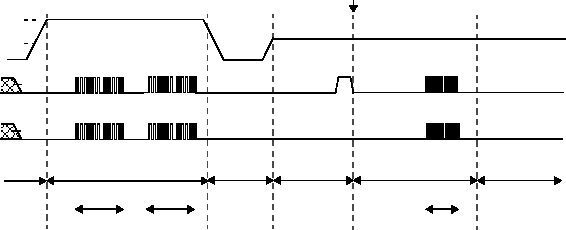
Figure 2.4: On-chip Debugger Execution Sequence
MCLR
VIH
RB6
(CLOCK)
RB7
(DATA)
Reset
Program/Verify Test Mode
Reset
Normal Run
Debugger Run
Normal Run
VIHH
Serial Programming
Communication
with PC
HALT
