-
TTL to RS232
-
Steve Walz of
armory.com says "Use a TTL HI
output for the RS232 *GROUND*!! Then you get +/-5VDC levels to fake out the
RS232. When TTL-GND goes HI, then a TTL-XMT LO looks like -5VDC and a "mark".
Even sign problems go away in hardware! When TTL-GND goes LO, and TTL-XMT
goes HI, it looks like +5VDC and a "space"! You can derive the two TTL signals
from one off an inverter or inverter pair! Then magically, you have direct
TTL to RS232 conversion!!
M. Adam Davis points out that we should "Just *make sure* the power supply
of the pic and/or the power supply of the other rs-232 device are not grounded.
ie, my bench power supply has +5v and ground, but the ground is grounded
to the house ground, SO is the computer's rs-232 port. I can't use this trick
without isolation. This also means that any interaction with other external
devices requires some thoughtful planning." [Ed: this is only true if the
devices confuse signal ground and chassis ground. Remember that ground is
at DB25 pin 7, and not pin 1 Pin 1 is chassis ground, not signal ground.]
-
IDEA: Pin 2 on a peripheral connector (pin 3 on a host connector) will typically
rest at -12 as driven by the external device. My Fluke 77/AN reads about
-10 on pin 3 of the DB9 connected to my PC. Some people (Tom Engdahl at
http://www.hut.fi/Misc/Electronics/circuits/rspower.html)
have suggested using this fact to derive -12 for TX power. This makes sense
as we normally are not RXing as we TX. How about adding a diode, resistor
and big fat cap to provide a more or less steady source of -12v to drive
pin 3 below zero when the NPN is biased off?
Scenix did this on a
demo modem board,
Nationals app note for a
mouse actually skipped
the cap and Engdahl did something similar in a line buffer circuit
http://www.hut.fi/Misc/Electronics/circuits/rsbuffer.html
but he was using an external power source for extra juice so the amplifier
type would have to be changed from emiter follower to a voltage gain amp.
They did not use RTS as a source of +12 volts, connecting the transistor
to +Vcc (local +5 volts) instead. My thinking is that if RTS isn't at +12,
the peripheral shouldn't be sending anyway. In fact, if I bias this correctly,
setting up the TX pin as an input would allow the periperal to read the RTS
status without needing another IO pin. Here is a
circuit and board in
Eagle and a picture of the circuit
-
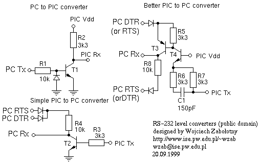
Wojciech
Zabolotny says
Take the higher voltages from the RS232 port (see
my circuits). T1,T2 & T4 may be almost any npn low power transistors
(eg. BC107). T3 almost any pnp low power transistor with UCEmax >=30V
(eg. BC177). Using of switching transistors is however recommended. Diodes
- almost any low power impulse diodes.
-
RS232 to TTL
-
Tjaart van der Walt says "I've
done this with a pair of simple transistor invertors for years without any
problems. Use the RTS line for the supply for the two transistors, and a
zener to limit the voltage going to the [processor]." Get 12V from the RS232
port on your [host] [ed: RTS, pin 20, is normally high (+12volts)], feed
it through a 10k resistor to the collector of *any* NPN transistor [ed: 2N222].
Ground the emittor. The input is via a 10k resistor onto the base, and the
output is on the collector"
http://www.wasp.co.za/~tjaart/images/ttl2rs232.jpg
-
Gerald Coe of
Devantech says "Feed the
RS232 into a 6k8 resistor. Connect the cathodes of two 1n4148's to the other
end of the resistor. Connect the anode of one diode to the PIC. Connect the
anode of the other diode to ground. Connect another 6k8 pull-up resistor
from the PIC pin to 5v. The data enters the pic upside down, but as you're
doing the Rx in software, that doesn't matter.
-
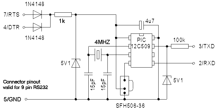
Ties Bows says "I use just a single 100K series resistor [and a 5V1
zener] to get 9600 Baud rs232 into a pic"
http://www.geocities.com/SiliconValley/Sector/3863/uir/Images/ir12b_schematics.gif

-
http://www.ise.pw.edu.pl/~wzab/picadc/picadc.html
Wojciech Zabolotny
says

See also:
RS-232@