Anyway I received Email form Tom Cicatelli. He said he had a been experimenting with an electronic stud sensor, and thought it would be useful for robots. He explained the stud sensor as a device that you slid it against a wall, and LEDs displays the relative density of the wall. I quickly went down to the local hardware store and purchased a hand held stud sensor from Zircon for only $11.99.
I had the stud sensor taken apart as soon as I was home. Inside I found a small circuit board, with one IC and a handful of resistors, capacitors and LEDS. The most interesting part was the three flat copper panels on the circuit borad. This was the sensor. Activating the device, the circuit calibrates itself to the surrounding area. If any object moves toward the sensor, its capacitance changes, and the LEDs display the change. The stud sensor can be adjusted and I found that I could sense my hand from several inches away. The display changes as I moved my hand closer. OK it can see my hand. Can it see a pencil? Yes. Can it see a piece of paper? Yes. Can it see glass? Yes. The stud sensor could see everything I could throw at it.
It took about 20 min. to connect the stud sensor to my Explorer Bot*. I connected the output of two of the LEDs to the robot. One signal indicated when the robot was too far from the wall, and the other indicated when it was too close. A few lines of code and I had a simple wall following robot. The stud sensor would keep the robot about 3 inches away from the wall without ever touching it.
Theory of operation for the stud sensor: The circuit sets up one oscillator and two one shot multivibrators. The two one shots are triggered by the oscillator at a constant rate. One multivibrators is connected to the copper plate, this is a sensor plate. The other multivibrator connects to a fixed capacitor. The difference between the discharge rates of the one shots determines the relative strength of the capacitive field.
Here is an update on another a very cool stud sensor.
I found a stud sensor at Home Base made by GB Instruments. Its about the size of a thick felt pen and has a 4 led display. It comes with 3 watch batteries and cost $10.
The sensor appears to be very accurate, just as accurate as the Zircon sensors but smaller.
OK now the fun part. I opened it up as soon as I got home, and to my amazement the circuit board had only a single-wire wedge shaped antenna. Since the circuit self calibrates I could make the antenna any shape I wanted. I connected a 12 inch clip lead, and it worked perfectly. I connected 3 clip leads, it worked perfectly.
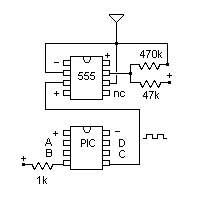
Next I examined the circuit board, and I expected some exotic chips... nope. One 8 pin chip connected to the antenna, it was a 555 timer. The second 8 pin chip is a PIC chip, maybe a 12c508.

I connected my oscilliscope up to the 555 and saw it out-putting a pulse stream. As an object moves toward the antenna the width of the pulses lengthened. Looks like the PIC chip simply calibrates the pulse width on startup, and if the pulse width stretched beyond a threshold ,say 40%, it turns on an LED.