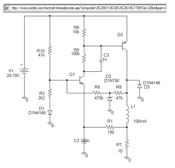
High Supply Voltage to Low(er) Voltage Coil with High Efficiency
by Richard Prosser

Operation: (comments by Russell McMahon)
-
L1 is relay R7 is relay current sense resistor
-
Q2 initially off so L1 top low.
-
Q1 base on via R10 with D2 acting as a "reference" voltage diode.
-
Q1 on turns Q2 on via R5.
-
Q2 on provides current to relay.
-
Relay current ramps up (I ~= V.t/L)
-
Relay current flows in R7 (here 10 ohms)
-
Voltage rising in R7 increases Q1 emitter voltage via R1 so Q1 is turned
off when V_R7 rises high enough.
-
Q1 off turns Q2 off.
-
Inductor "rings" (flips voltage polarity) and current in L continues via
D1 L R7 in a classic buck regulatior fashion.
-
Top of L1 flipping down in V pulls down path via R8 R9 and lowers Vbase of
Q1 to add hysteresis to turnj on again point for Q1.
-
When I_L falls enough Q1again turns on anc cycle repeats.
Archive:
See also:
-
http://www.4qdtec.com/srd.html Really interesting little
circuit for driving solenoids or relays. The schematic does not identify
the components, but I believe the resistors and diodes are numbered from
the top down, and the transistors are numbered from the left to the
right.

