The 1284 standard goes beyond describing new data transfer modes and actually defines the mechanical interface and the electrical properties of a compliant parallel port. Many of the problems associated with parallel port-attached devices arise from the fact that there has been no standard for the electrical interface for the parallel port. The DB25 female connector has become standard for the PC or host connector, but there have been many different implementations of the drivers, resistors, capacitors, etc, for electrical the interface.
The 1284 committee felt that it was paramount to define what these properties should be in order to meet the following objectives:
To meet these objectives, the standard defines the connectors, electrical interface, and cable requirements.
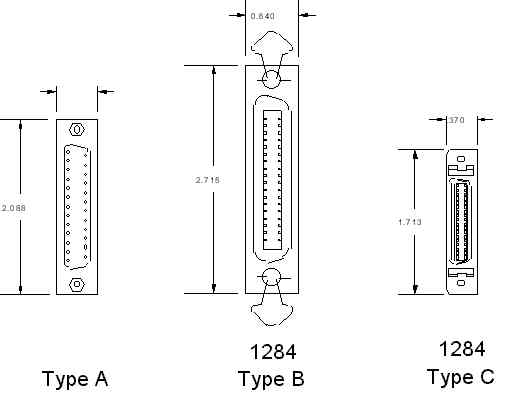
The standard identifies three types of connectors for a 1284 interface.
Figure 1 shows what these connectors look like.

The type C connector is the one recommended for new designs. This connector offers a smaller footprint than the previous connectors, has a simple-to-use clip latch for cable retention, and provides for the easiest cable assembly with the optimal electrical properties. In addition, a cable assembly built with this connector provides for two more signals. These signals are Peripheral Logic High and Host Logic High. These signals may be used to determine if the device at the other end of the cable is powered on. This enables some degree of intelligent power management for 1284 interfaces.
Also:
See also:
Comments:
Hi friends,
I am searching for footprints (to add on PCB) of ieee1284b 36 pin connector (parallel port connector found on printers)
for 90 degree type connector. Please help me to find.
Post either a link
or the exact footprint