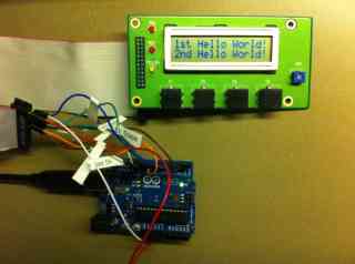
The Big Picture
by Bud Justen
The following is a description of testing the LCD Front Panel Set: 2x16 LCD w/HD44780 controller.
The following steps apply:
1. Attach 40 pin IDE cable with red stripe to pin 1 of LCD Panel.
2. Attach breadboard type jumper wires (Qty 9) between IDE and Arduino PCB using figure 1.
| Figure 1: Cable Connections between LCD Panel and Arduino UNO for LCD Test using 4bit mode
|
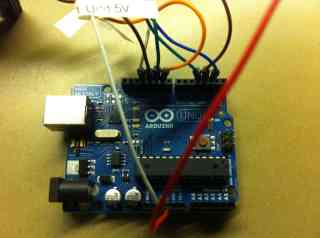
3. Before applying any power, verify connections as shown in these photos (click for larger version)

The Big Picture |
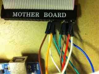 The Even Pins 2,6,12,14 |
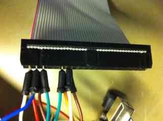 The Odd Pins 1,3,5,11,13 |
 Pin 1 |
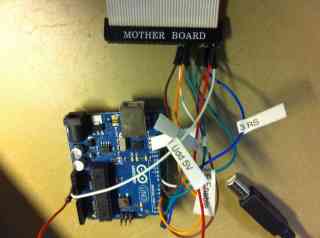 Pin 2 |
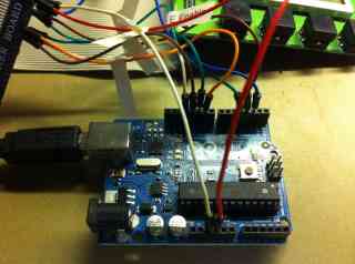 Pin 3 |
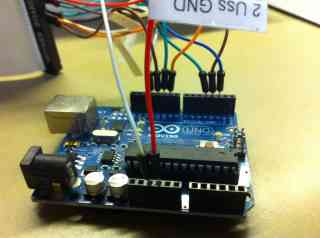 Pin 4 |
4. Attach USB cable from PC to Arduino UNO PCB.
5. Startup Arduino IDE
6. Open sketch LCD_write2lines.pde
7. upload to Arduino PCB
8. Upload should complete with no errors and "1st Hello World and 2nd Hello World" should appear across 2 Rows of the LCD
9. If Display appears dark, adjust contrast potentiometer next to LCD.
Attached 40 pin IDE cable to LCD Panel with Red Stripe end to pin 1.
Attached 9 jumper wires from IDE to Arduino UNO PCB
The notch side of IDE cable has ODD pins (1,3,5,11,13) jumpered to UNO PCB
The non.notch side of IDE cable has even pins 2,6,12,14) jumpered to UNO PCB
If only the write to display is required, then the RW line on pin 6 of the LCD panel can be grounded. This would require one less jumper wire and would free up one of the Arduino I/O ports. I grounded pin 6 and the program worked fine.
#include <LiquidCrystal.h>

// set constants to screen dimensions:
const int numRows = 2;
const int numCols = 16;

//specify which Arduino I/O pins = RS,RW,E,DB4,DB5,DB6,DB7
LiquidCrystal lcd(2, 3, 4, 9, 10, 11, 12);

void setup()
{
	// set up the LCD's number of columns and rows:
	lcd.begin(numCols,numRows);//specify screen dimensions
	lcd.clear();//clear the screen
	lcd.setCursor(0,0); // set cursor to col 0 row 0
	lcd.print("Wait a second");// print from cursor location
	delay(1000); // wait 1 second
	lcd.setCursor(0,0); // set cursor to col 0 row 0
	lcd.print("1st Hello World!");// print from cursor location
	delay(1000); // wait 1 second
	lcd.setCursor(0,1); // set cursor to col 0 row 1
	lcd.print("2nd Hello World!");// print on row 1
}

void loop() {}